Home Electrical question

mbalbritton

#@$%!
Joined
Mar 22, 2005
Location
Lakeland, FL
I have an antiquated Emergency Heating System in my house. It runs on 220 and is basically a heating coil in the wall with a blower. A real Energy sucker that I didn't want my wife even accidentally turning on. One of those systems that you'd have to take a second mortgage out on if it ran for an hour.

anyway, behind the controllers that are mounted on the walls is 220 and 110 wiring. and what caught me off guard was that the white wire for both the 220 and the 110 are run together. as in twisted together and wire nutted. Anyone know why? my best guess is the heating coils use 220 and the blower uses 110 and both need to get their signals from the controllers. Since the Black isn't run together (220/110) the respective circuits still only see 220 or 110.

yes no maybe?
 
Got a pic?

With 220 the white wire would have 110 on it. Unless its 220 with a neutral, in which case you most likely would have black and red hot wires, and a white neutral.

With 110 the white wire is a neutral, and at the same potential as ground.

Unless they used the white side of the 220 to get the hot for the 110 and made the black of the 110 a neutral (as in a jack legged repair, if the 110 hot was grounded, they swapped and made it the neutral) I don't know what's going on.

What is happening with said circuits in your panel?
 
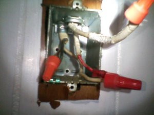
Wife has the Camera down in Florida so you get the crappy cell phone pict.
coming thru the top center of the box is the 220, and I had it wrong, the Red from the 220 is twisted together with the white from the 110.
now, I know the only breakers that are off in the panel are the 220's, but with my tester I'm not getting any signal from any wire in this box. I HATE electrical.

I put the two orange caps on there just FYI. those went to the controller that I removed.
 

Attachments

  • 0717091211a.jpg
    0717091211a.jpg
    35.5 KB · Views: 174
So the wire coming in the center is coming from the panel, and the wire on the left is going to the heater coil? So you don't have 2 circuits there, only one 220 circuit, with the center cable going to the panel, and the cable on the left going to the heater.

If that's the case, the red wire tied to the white wire is constantly sending power to the coil. The other 2 wires, with the orange wirenuts on them, is the 2nd leg of the 220 being broke through the switch (controller).

IE, the coil won't work with 110 (one leg of 220) going to it, so when you opened the switch, (breaking one leg of the 220) the heater turned off, and when you closed the switch, it turned back on. So if you put the 2 wires with orange wire nuts together, the heater would run continuously unless you turned the breaker off.


If that's not right, where are the 2 wires going?
 
old outdated ? huuh... most auxiliary heating circuits are just what you described. 220v Heat coils. My heat pump runs several hours per day on the coils in the winter. Granted its old and a newer unit might be better but when its hard to pull heat from the air at 20deg..

Also FWIW: electric heaters all are equally efficient. It takes X number of watts to make X BTU. Typically heat is a waste/byproduct product of electrical stuff. So if your heater isn't making as much heat it isn't using as much juice... Any thing beyond actual heat is simple better construction/materials (last longer) or more bells and whistles and safety items or possibly better at putting the heat where you want it.
 
Back
Top