Will Carter
Well-Known Member
- Joined
- Mar 23, 2005
- Location
- Burlington
Machining/Mechanical question...
I'll try and explain it without a picture...cause right now I've got no software to draw a picture on...no not even Micro-paint...
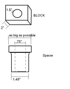
We've got a 1.5" round hole in a piece of 2" thick steel. We really need this hole to be .75" to insert the same size bolt and be able to connect another part with some hefty torque...say 175lb-ft .
So we need a 'reducer' of sorts. However, welding in a 'reducer bung' is not an option. Can't weld to the 2" piece cause we're gonna need to be able to swap back and forth from the 1.5" hole to the .75" 'adapter'.
The .75" bore in our bung also needs to be centered in the 1.5" original hole.
I'm thinking I'll start with a piece of 2" round, leave a .375" lip and turn the remaining length down to 1.498" to fit inside my hole. Drill in a .75" hole and we have a centered bung. Now just make one for the other side and we're set....but here's my question...(that took long enough, right?)
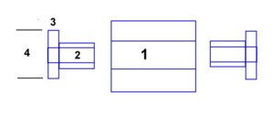
Do I need to make these two adapters touch in the middle or can I just make them a shorter size with a gap in between when they're torqued (remember, 175ftlb)?
If they need to touch in the middle, how much distance should I leave to make that 175lbft transfer from clamping the two adapters together to actually holding the adapters onto the original piece of 2" plate? I'm thinking this is going to be a .003"-ish number, right?
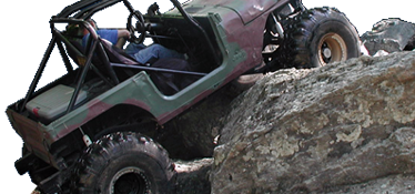
The 'part' is actually a suspension flex joint that will be mounted to this 2" plate in single shear...so it will see those sort of forces if you can imagine...
I hope that was clear enough...


 I want to see this picture, it's got me curious!


