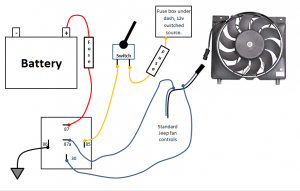
Can someone educate me on 5 pin realys? I understand the basics of a relay, and have wired up 4 pin relays for off road lights etc. My son wants to be able to manually turn on the electric fan in his XJ and found this diagram, I'm pretty sure it isn't correct as most of the time I've seen (and research shows) 30 is for the battery. Supposedly this diagram shows how to wire it up and still maintain the "Stock" ecm control of the fan, but it enable you to turn the fan manually any time.


You are using an out of date browser. It may not display this or other websites correctly.
You should upgrade or use an alternative browser.
You should upgrade or use an alternative browser.
5 pin relay manual fan
- Thread starter No fries
- Start date
Jeff B
Thanos was right
- Joined
- Dec 23, 2006
- Location
- Lincolnton N.C.
It's switching between battery power and ECU power.
Jeff B
Thanos was right
- Joined
- Dec 23, 2006
- Location
- Lincolnton N.C.
I dont see why it wouldn't.So this is correct and would work?
Keith1138
Well-Known Member
- Joined
- Nov 18, 2015
- Location
- Harrisburg NC
Holy crap you read my mind. I was about to post the same exact thing because I want to do this to mine.Can someone educate me on 5 pin realys? I understand the basics of a relay, and have wired up 4 pin relays for off road lights etc. My son wants to be able to manually turn on the electric fan in his XJ and found this diagram, I'm pretty sure it isn't correct as most of the time I've seen (and research shows) 30 is for the battery. Supposedly this diagram shows how to wire it up and still maintain the "Stock" ecm control of the fan, but it enable you to turn the fan manually any time.
Sent from my SM-G981U using Tapatalk
Fabrik8
Overcomplicator
- Joined
- May 27, 2015
- Location
- Huntersville
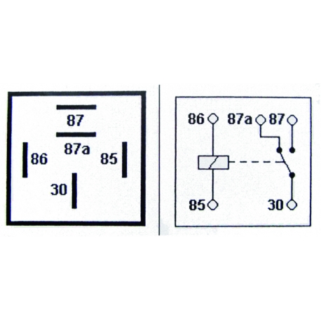
It will work fine. It's a single pole, double throw (SPDT) relay, which means that terminal 30 is either connected to terminal 87 or to terminal 87a depending on whether the relay coil is energized or not. Term 30 is normally connected to term 87a, and then switches to term 87 when energized.
So with the relay off, term 87a is connected to term 30, which means that the normal fan wiring is directly connected (the relay "splices" the wires together). With the relay on, term 87 is connected to term 30, which connects the fan to battery power instead.
Term 85 and 86 are the relay coil terminals, so you just need a 12V signal (from the switch) and a ground reference.
Yes, term 30 would often be connected to the battery for certain applications. Relays are just a set of switch contacts, and polarity doesn't matter, so how you connect the switch contacts depends on what you're trying to achieve.
Relays are very simple when you look at a diagram:
- Joined
- Apr 16, 2005
- Location
- Sharon, SC
What he said.
One caveat.
When the cheap relay fails.
I mean if, if - sure thats it - if the cheap relay fails..
Your ECM wont turn fan on.
Take away?
Use a quality relay
One caveat.
When the cheap relay fails.
I mean if, if - sure thats it - if the cheap relay fails..
Your ECM wont turn fan on.
Take away?
Use a quality relay
Tim C
Wizard
- Joined
- Jan 22, 2007
- Location
- Fayetteville
It's been covered above but think of pin 30 as the common pin. If you have two different loads you want to power from the same fuse, 30 goes to fuse, 87a and 87 goes to the loads, like high and low speed fan or high and low beam headlight.
If you have one load you want to switch between two power sources, it's like the diagram. Load goes to 30, 87a and 87 are powers in.
Those pins don't care which way they are flowing current, they are just a switch. 85 and 86 pins for the coil in the relay may matter. If the relay has a diode across the coil to prevent a voltage spike when the relay is commanded off it may have a diode that may fry a computer for example. A lot of cheap relays don't have the diode.
It will work fine. It's a single pole, double throw (SPDT) relay, which means that terminal 30 is either connected to terminal 87 or to terminal 87a depending on whether the relay coil is energized or not. Term 30 is normally connected to term 87a, and then switches to term 87 when energized.
So with the relay off, term 87a is connected to term 30, which means that the normal fan wiring is directly connected (the relay "splices" the wires together). With the relay on, term 87 is connected to term 30, which connects the fan to battery power instead.
Term 85 and 86 are the relay coil terminals, so you just need a 12V signal (from the switch) and a ground reference.
Yes, term 30 would often be connected to the battery for certain applications. Relays are just a set of switch contacts, and polarity doesn't matter, so how you connect the switch contacts depends on what you're trying to achieve.
Relays are very simple when you look at a diagram:
^^ this is what I was looking for. Yes I wanted to confirm it would work but I wanted to understand the NC and NO 87A and 87 plus the "flow"
What he said.
One caveat.
When the cheap relay fails.
I mean if, if - sure thats it - if the cheap relay fails..
Your ECM wont turn fan on.
Take away?
Use a quality relay
Plan on using a Nappy $25 relay.
Fabrik8
Overcomplicator
- Joined
- May 27, 2015
- Location
- Huntersville
^^ this is what I was looking for. Yes I wanted to confirm it would work but I wanted to understand the NC and NO 87A and 87 plus the "flow"
I figured that's what you were going for. Just saying "wire it like this" doesn't really help you learn anything.

Jeff B
Thanos was right
- Joined
- Dec 23, 2006
- Location
- Lincolnton N.C.
I'm not a good teacher at all. It's my lazy side..
Fabrik8
Overcomplicator
- Joined
- May 27, 2015
- Location
- Huntersville
If the relay has a diode across the coil to prevent a voltage spike when the relay is commanded off it may have a diode that may fry a computer for example. A lot of cheap relays don't have the diode.
That is a good point.
If the coil does have a flyback diode across it, then then schematic in the first post has the coil connections backwards. Term 85 should be the ground and term 86 should be +V. Diode is not needed if controlled by a switch from a battery/ignition power source.
Else, it doesn't matter. It also doesn't matter if the coil has a suppression resistor across it instead of a diode, because resistors don't have polarity either.
Keith1138
Well-Known Member
- Joined
- Nov 18, 2015
- Location
- Harrisburg NC
If you were wanting to wire it into a 3 prong rocker switch you will just run the out put wire from the switch to the 85 slot on the relay? Assuming you have power running to the switch panel.
I know very little about wiring.

Sent from my SM-G981U using Tapatalk
I know very little about wiring.
Sent from my SM-G981U using Tapatalk
So I tried it last night and I kept blowing fuses in the switch. Double checked connections (correct to the diagram), Tried several scenarios with the OEM wiring connected and without 87a 87 and 30. 30 always went to the fan "positive"
Then I set up just a simple test as I couldn't find a short anywhere. Battery was connected to 87, 12V test light connected to 30 and grounded, 86 to ground and 85 went back to battery, with a momentary switch. Soon as I hit the momentary switch the relay let out all of its smoke! WTF?
I did some research and the relay I have is a napa AR204 which says it has a diode across the coil. Could the diode been creating this problem?
https://www.napaonline.com/en/p/ECHAR204_0169415046
Or is it how the fan is "energized"? by grounding it instead of sending power to it. I'm assuming that the green wire (on the vehicle) blue (schematic) is the power source and not the black wire.
Could the fan be faulty too?. I did a quick jumper to test it and the fan did spin when it got 12V. (not from the computer)
93XJ
@Keith1138 we have a 3 pronged LED switch, one was to the fuse block for source of power, the load went to 85 and the 3rd was a ground for the LED light. But evidently I know less than I thought because I went thru 4 5a fuses and one relay.
Fabrik8
Overcomplicator
- Joined
- May 27, 2015
- Location
- Huntersville
I did some research and the relay I have is a napa AR204 which says it has a diode across the coil. Could the diode been creating this problem?
https://www.napaonline.com/en/p/ECHAR204_0169415046
It's the diode. Per my post above, the schematic picture that you posted has the coil connections backwards. That only matters IF the relay has a diode, because the diode would face the wrong direction, making a short circuit between power and ground in that case (SMOKE).
If the coil does have a flyback diode across it, then then schematic in the first post has the coil connections backwards. Term 85 should be the ground and term 86 should be +V. Diode is not needed if controlled by a switch from a battery/ignition power source.
In other words, whoever made that schematic didn't follow normal relay convention, which screwed you because you happened to use a relay with a diode.
This is the difference between how you can hook something up, and how you should hook something up.
Last edited:
Keith1138
Well-Known Member
- Joined
- Nov 18, 2015
- Location
- Harrisburg NC
Any way you could make a condenses version for us to follow?It's the diode. Per my post above, the schematic picture that you posted has the coil connections backwards. That only matters IF the relay has a diode, because the diode would face the wrong direction, making a short circuit between power and ground in that case (SMOKE).
In other words, whoever made that schematic didn't follow normal relay convention, which screwed you because you happened to use a relay with a diode.
This is the difference between how you can hook something up, and how you should hook something up.
Like.....
87a--> wire from switch
87--> wire that went previosly to the fan
30--> directly to fan
85--> ground
86--> ???
Sent from my SM-G981U using Tapatalk
Yeah,It's the diode. Per my post above, the schematic picture that you posted has the coil connections backwards. That only matters IF the relay has a diode, because the diode would face the wrong direction, making a short circuit between power and ground in that case (SMOKE).
In other words, whoever made that schematic didn't follow normal relay convention, which screwed you because you happened to use a relay with a diode.
This is the difference between how you can hook something up, and how you should hook something up.
I didn't see that post before I started.....
Back to the parts store, but with the diode, on the coil, it can't be wired to come on via computer or switch, that I can think of with a more expensive relay( @Ron ) lol lesson learned.
Sent from my SM-G973U using Tapatalk
When I get it yeah, but work and rain has gotten in the way. I learned how not to hook it up last night.Any way you could make a condenses version for us to follow?
Like.....
87a--> wire from switch
87--> wire that went previosly to the fan
30--> directly to fan
85--> ground
86--> ???
Sent from my SM-G981U using Tapatalk
Sent from my SM-G973U using Tapatalk
Fabrik8
Overcomplicator
- Joined
- May 27, 2015
- Location
- Huntersville
Yeah,
I didn't see that post before I started.....
Back to the parts store, but with the diode, on the coil, it can't be wired to come on via computer or switch, that I can think of with a more expensive relay( @Ron ) lol lesson learned.
Sent from my SM-G973U using Tapatalk
No, you can go back and buy the exact same relay that you already bought. You just need to wire the switch and ground to the proper terminals on the relay.
In the schematic picture that you posted, the picture shows:
Switch to term 85
Ground to term 86
But because of the diode, the proper way is:
Switch to term 86
Ground to term 85
That's it, no other changes. It should be wired that way whether there is a diode or not, because then it doesn't matter whether there is a diode or not.
The people who drew the schematic almost knew enough to wire it properly, such that it wouldn't matter if there was a diode or not.
Last edited:
Fabrik8
Overcomplicator
- Joined
- May 27, 2015
- Location
- Huntersville
So here's what you bought, which will work perfectly for what you need. This picture shows the diode, which will make sense if you understand how a diode functions.
If you wire it like the schematic you posted (term 30 to power, term 86 to ground), the diode faces the wrong way, and current flows through the diode and makes a short circuit.
That's why the schematic should say:
Switch to term 86
Ground to term 85
Then the diode blocks current because it's facing the proper direction, and everything works great.
Last edited:
So to @Keith1138 in his terms
85 --> Body Ground
86 --> Fused Switch terminal
87 --> Fused Battery wire
87A -->computer splice
30 --> fan splice
Splice should be in wiring harness not at fan side of plug. So when/if the fan is replaced you can just replace the fan and not have to re wire it again.
85 --> Body Ground
86 --> Fused Switch terminal
87 --> Fused Battery wire
87A -->computer splice
30 --> fan splice
Splice should be in wiring harness not at fan side of plug. So when/if the fan is replaced you can just replace the fan and not have to re wire it again.
Fabrik8
Overcomplicator
- Joined
- May 27, 2015
- Location
- Huntersville
So to @Keith1138 in his terms
85 --> Body Ground
86 --> Fused Switch terminal
87 --> Fused Battery wire
87A -->computer splice
30 --> fan splice
Splice should be in wiring harness not at fan side of plug. So when/if the fan is replaced you can just replace the fan and not have to re wire it again.
Yes, that's right.
The "computer splice" is actually power supplied from the OEM fan relay (which is controlled by the computer); you're not connecting anything to the computer directly. I'm just saying that to help explain how everything is working together.
Keith1138
Well-Known Member
- Joined
- Nov 18, 2015
- Location
- Harrisburg NC
Thank you so much!!So to @Keith1138 in his terms
85 --> Body Ground
86 --> Fused Switch terminal
87 --> Fused Battery wire
87A -->computer splice
30 --> fan splice
Splice should be in wiring harness not at fan side of plug. So when/if the fan is replaced you can just replace the fan and not have to re wire it again.
I struggle with understanding wiring besides the basic stuff like always use wire nuts and leave a little bit of bare wire exposed.
I know use butt connecters that sodder and heat shrink and use coverings.
Again thank you.
Sent from my SM-G981U using Tapatalk