need to make one of these............

Cperry

Well-Known Member
Joined
Apr 24, 2005
Location
Durham, NC
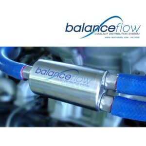
This is for a 6.5 chevy, heads and block in the rear have heat issues, a system has been designed to exit coolant from the rear ports on the head back to thermostat crossover pipe to help eliminate this problem. 2 hoses come from the block off plates into collector bottle then the one goes to t-stat crossover. the quote below is what they say it is. i underlined they didn't.

"The system routes coolant from the two rear water ports to a specially configured, flow balancing tank mounted on the driver's side of the intake manifold. Coolant is then routed from the balancing tank forward to a special hose fiting installed in the coolant crossover manifold."

I personally think it is hollow inside and just acts as a collector combining the 2 ports. The kit is $470 dollars for a couple of hoses, that tank, a tapped crossover pipe , and some fittings for the rear blocckoff ports.

I want to make the bottle, my only idea so far has been cut two AC dryer bottles and tig them together and tig in fittings. besides the bottle there is nothing to the kit. Any ideas on what and how to make it and what if anything is inside that bottle to make it specially configured.
 

Attachments

  • 100217_3.jpg
    100217_3.jpg
    21.3 KB · Views: 314
I imagine it'd be nothing more than a series of perforations or "holes" that would force the flow to equalize pressure between both chambers.

No real knowledge just an asumption
 
Could it have two 1 way valves in the side with two hoses?
I can't really think of any reason water coming from one hose going to the other one might cause a problem?
But maybe?
Other than that I can't see what would be in that?
Got a link with more information? I'm sucking at the google, and work seems to be blocking most of the hits anyway?
 
It probably is set up with internal check valves
 
I doubt there are check valves, b/c the way a cooling system works seems there would be no reason for them, but if you can explain to me why there would be a check valve I may buy into it.

Coolant is always going to flow to the lowest pressure, towards the top of the radiator, so it would never flow backwards so no need for a check valve
 
I imagine it'd be nothing more than a series of perforations or "holes" that would force the flow to equalize pressure between both chambers.
No real knowledge just an asumption

I thought about this or baffles, but once full of coolant and pressurized would either of these really balance the flow any. I don't think it would.
 
I doubt there are check valves, b/c the way a cooling system works seems there would be no reason for them, but if you can explain to me why there would be a check valve I may buy into it.
Coolant is always going to flow to the lowest pressure, towards the top of the radiator, so it would never flow backwards so no need for a check valve[/QUOTE
can't explain why other just to justify the cost
 
"specially configured, flow balancing tank" sounds like marketing hype. Its a 2:1 but the 1 is same diameter as the pair of 2's?
Premise is to move the hottest fluid out of the blocks rear side instead of back through the intake. Does this really cool the last cylinders better than the stock setup? Hard to say. If the engineers at GM did their damn homework, this external output would not be necessary. Its known as thermal analysis and Flomerics makes a damn good tool for solving this problem.Guess ole Roger Smith cut that out of the design process like was done with some of the other stoopid junk, read Vega and 350 diesel, he blessed.
My money would be on core problems with the 6.5 or low output water pump. What are the racers doing? Has Gene Banks of Banks Engineering endorsed this idea?

Just my $0.02 :beer:
 
ya i understand the premise, there is alot that goes into the design, banks is not the foremost knowledge on all diesels, in fact i would say he does not know much about 6.5's. The guy that designed this one is very reputable, knows his stuff and hired a thermal engineer and tested the motor ect. ect. hence the high price tag i would asume. And yes GM fouled up not new news.
 
Get a large piece of aluminum tube and weld some ends on it. Might look better than two A/C units welded together.

Get me a size you want, I may be quitting where I work to go to somewhere else, but a friend could make you something (his TIG welds look better than mine anyways).
 
Well if we were talking about turbos or charge coolers Banks may be a good reference, but since were not. it really does not take a rocket scientist to add a manifold with a turbo on it which is all they did in this case.
 
have any info on the cooling flow path in/out of the engine? Is it standard or reverse flow? Also do you have a pressurized coolant overflow container (like on the PSDs)

without knowing the details, off the top of my head <-pun here are a few things to consider

1) is overflow is like PSD, do like my old coolant filter did, too a 3/8" line and simply pull a lines off each head and dump it into the overflow, they wouldn't be tied and both would flow the same based on system pressure.( the PSD coolant filter didn't really flow a ton and would be perfect amount for this)

2) consider finding a pressure port near the water pump and simply T it to each head and push (instead of pull) some cooler coolant back there. Under pressure things should even then selfs out...

3) pull both heads together and make it part of the heater loop
 
Back
Top