Suspension Theory

Mac5005

Well-Known Member
Joined
Oct 19, 2005
Location
Rocky Mount
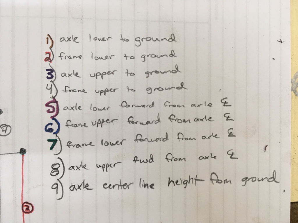
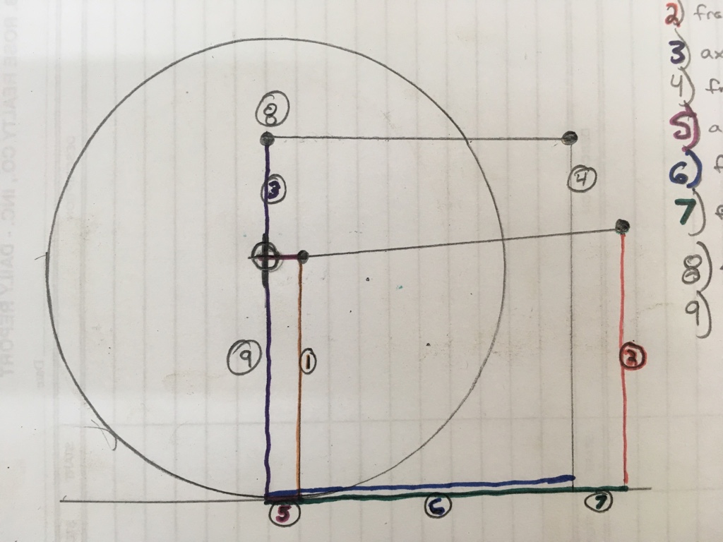
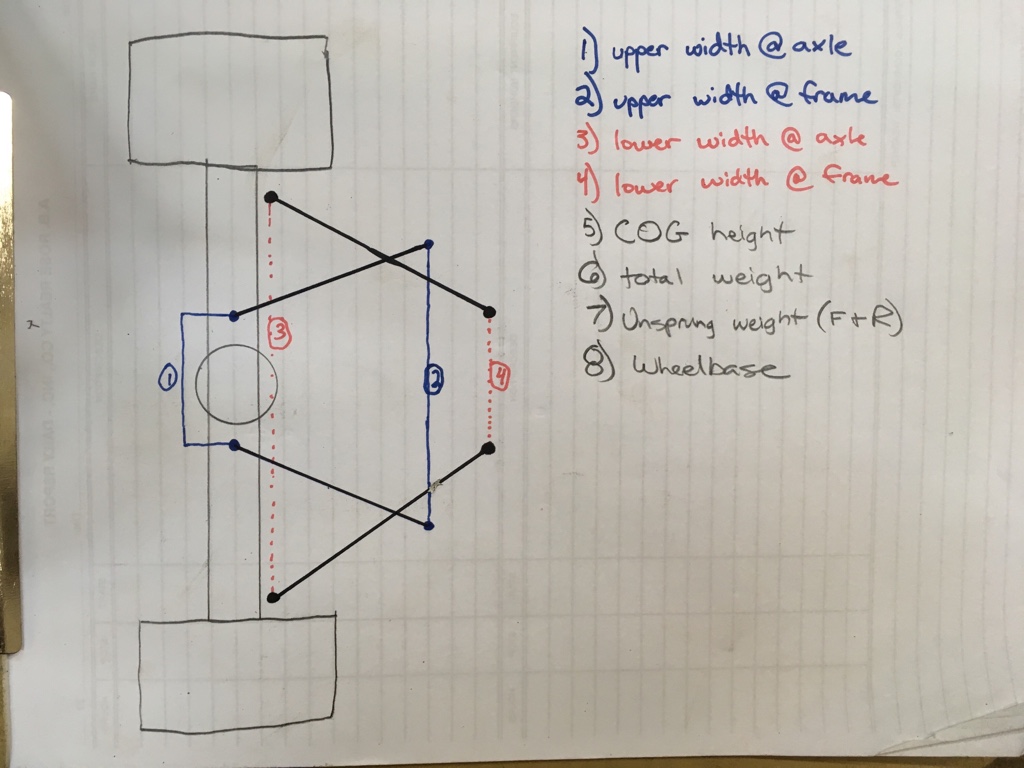
I intend this thread to be a collection of suspension theory and design/engineering principles that are proven to work. This is mainly coming as a spinoff from a few other threads, and recently from Daves thread on springs and shock setup. This will be a little slow to develop at first, as its going to take some time to arrange my thoughts, and try to back them up with pictures to aid in understanding.

I am by no means an engineer, and I intend to take many liberties with the principles at play to aid in explanation and understanding of vehicle dynamics.

Many of these thoughts, theories, and designs are not my creation, but are a collection of thoughts from those much smarter than me, that choose to share them on the web.

These theories are constantly evolving, and nothing is written in stone.

A good quality suspension, one "that works" , is comprised of a quality design that compromises all aspects to a well balanced package that matches the desired usage. There is no solid concrete design or answer.

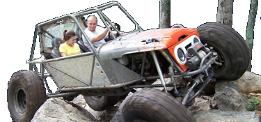
An ultra4 buggy or "car" is built and designed to perform under unreal circumstances at high speeds for miles and hours at a time with minimal part failures. However it also must perform well in technical rock sections as well.

A mud truck, or even a mega truck has to get the power to the ground nearly instantly, yet rarely sees inclines, or off camber sections. It also rarely sees high traction surfaces.

A trophy truck has to perform well for hours at time with minimal failures at high speeds. Ground clearance is less of a concern than Ultra4, and no compromises can be made with suspension compliance.

A cone dodger or comp crawling buggy sees extreme angles both front to rear and side to side. It must be able to make climbs on both low and high traction surfaces, but is rarely operated at speed.

So where does a semi-hardcore trail rig fit in? Or a Dual purpose hardcore rig, that still sees some street use.

Each one of these types of vehicles requires a slightly different design and setup. Shock selection and tuning is very different for all.

A great setup in one area, may mean a huge compromise in another area. This is the common theme. The hard part is to design a rig that does everything well, and give up as little as possible.

I hope to start off with the easier stuff, and then increase in difficulty as the conversation and thread progresses.
 
So to begin, lets start with some simplifying.

I intend for this information to be based primarily on solid axles and link type suspensions.

A few explanations and definitions. Ill do the text first, then try to come back and add images. These are not engineering definitions and are dumbed down to aid in explanation and understanding.

To understand these and aid in explanation, lets only talk about the rear suspension first.

Antisquat.(AS) This is the reaction of suspension movement to torque and traction. As a vehicle accelerates forward, weight is transferred rearward. How much weight depends on COG height, wheel base, and acceleration rate. The extra weight transferred will "squat" the rear suspension. Antisquat (AS) is the reaction of the link design, to slow down this "squat".

When accelerating, the tire is trying to rotate forward and down, while the pinion is trying the opposite. The pinion is trying rotate upward and back.

Antisquat in the rear, is the links "pushing" the axle away from the frame.

The relationship of the pinion trying to rotate upward, and the links force (based on geomentry) onto the frame, create anti squat.

If you have 100% AS, then as the rig accelerates, the rear suspension will not change position. It will stay at ride height (RH). This is independent of front lift and vehicle pitch.

Antisquat (AS) does not change actual amount of weight transferred. It affects the path the weight transfer takes on the way from the COG to the tire contact patch, and the speed at which the weight is transferred. Regardless of any Anti value, the weight will still be transferred. Remember weight transfer F/R during forward acceleration, is dependent on COG height, wheel base, and Accel rate.

0% AS, the weight transfer is completely through the spring and shock, and 0% through the links.
100% AS, the weight transfer is completely thought the links, and 0% through springs and shocks.
150% AS, the weight transfer will cause the rear to rise above the static RH position.
-50% AS causes the weight transfer to cause faster squat than 0%, possibly to the Bump position*

You do not want the Antisquat to increase in droop.

As the rig goes uphill on an obstacle. Lets use a waterfall style rock for example.

As you go uphill, and the rig pitches, the springs are still pushing the axle from the frame, but now, this force is not parallel to gravity.

Gravity still pulls the sprung mass downward vertically, but now the springs are at an angle. This will always result in the suspension moving towards droop as you go uphill.

Too much Antisquat will cause wheel hop. This is from the links pushing the axle away from the frame. The higher the AS, the harder the "push". Once this gets to be too much, it shifts the weight away from axle. This momentary push of weight "upward" is enough to reduce the traction of the tire, and the tire slips and spins.

If the tire slips, it has less traction, and therefore less AS. the suspension settles. As the suspension settles, the weight returns to the contact patch, traction rises, AS rises, and the links begin to push the chassis back "up" again. This happening over and over is wheel hop.

If I lost you, go stand on a scale with a weight on your head. Now lift the weight higher above your head, and watch the scale.

As you begin to push the weight upward, the weight on the scale increases. As your arms extend and the weight stops accelerating upward, the weight on the scale drops. As the weight stops moving and your arms are extended, the weight on the scale returns to the same # as before.

Too little antisquat will not push the chassis up from the axle, possibly putting the suspension to full bump at max acceleration. This would be terrible if you were accelerating, and then hit a big bump, as the suspension would already be at full bump, and there would be no travel to soak up the impact.

Too much or too little antisquat depends on many factors for each rig. The main difference is traction. a light weight rig with stickies will be far more finicky with increased AS, than a heavy rig with old cold TSLs.

You can compare rigs against one another, and what works, but there is no concrete number or limit.
 
Last edited:
IC - instant center. Most often the instant center that we are concerned with is the side view instant center. This is the imaginary point in space that the upper and lower links would intersect, if extended, in the side view only.

This is the point needed to draw an antisquat line or line of action from the tire contact patch to the IC.

This line of action or antisquat line is used frequently.

f76c9da57a9f2017c976b21e720e054b.jpg


Two things to consider with IC,

1)the horizontal distance from the rear axle centerline to the IC.

2) vertical height of the IC from the ground.

These two numbers can be changed independently of one another for different effects with moving multiple link locations.

The can be changed independently but are fully dependent on one another for things such as antisquat and the slope of the line of action.


RC- roll center.

This is the point at which the sprung mass pivots about, when viewing the rig from in front or behind.

The chassis and sprung mass "rolls" around this point when going around a turn, or when off camber.

Most often what's important with RC is the vertical height from the ground.

A higher roll center will result in more sideways chassis displacement as the axle articulates.


RM- roll moment.

Same thing as roll couple. Different sources use different words to describe the same action.

This is the vertical distance from the COG to the RC. This is the leverage the sprung mass has on the link geometry in roll.

5bb4d8009aa2672ccf8b758f0c3ec217.jpg


48b8af774ee8c0d786726b1ed5318e12.jpg


- saved for more definitions.
 
Last edited:
So let's start with the basics. Lol

We have to get started somewhere. There always has to be a start in order to make it better.

To me, a quality suspension is one that works. It's designed the best that it can be, given the design constraints and compromises made.

The next part to a quality suspension is
Getting the "right" springs and shocks for the intended usage.

After that, a quality suspension is tuned to the drivers liking.

There is no replacement for seat time, and experience that translates to confidence in your rig.

You tune your suspension to how you want it to perform.

To use slawsons bomber u4 cars as an example: the same tuner has tuned these rigs, and knows a great starting point. However, Im willing to bet that no two cars with different drivers are set up absolutely identical.

This is why you need to tune the suspension for what you plan to do, and what feels good to you.

A knowledgeable tuner can watch the rig and understands what changes are needed and offer suggestions, but in the end, it comes down to what works and feels better to you.

This is why it's also important to tune for what you plan to do. Tuning the suspension for cone dodging will not work well for ultra4. Tuning for ultra4 or Baja type stuff will beat you to death on slow crawling trails.

Again you have to compromise and focus on what's important.

So to begin start with a few measurements and get them in the calculator.

Some are easy, some not so much.

cc91d62a487bb46a3ca1de5a0fc203ec.jpg


66f9c9b1d916603280d724e5c1efb716.jpg


38a910453dcdd6ec42cdcf50a5b419bc.jpg


71cb1639989ca10b52cebbc33202c2ee.jpg


If you are working on an already built rig, write down your current setup, as well as an acceptable range of dimensions that will fit your chassis. This will save you time back and forth from computer to driveway.

If you are working on a new build or a buggy, you will have to get creative on imagining where links will be. Set yourself some goals.

The first are some chassis measurements.

Cog height. Look at images of things already built and estimate. There is tons of info on the web to find the cog height. I'm not explaining all of this. Google it.

If you are building a buggy, look at something already built that you like, and is similar. And guess.

How much suspension travel? And what is your static position. This will result in something like : 14" travel, 7 up, 7 down.

Guess at what the belly height is, or guess at a distance from the top of the tire to the cam centerline, or top bell housing bolt. Make an educated guess and go with it. It'll be ok.

Make a guess at overall weight, use google, use scales, whatever it takes. Be realistic.

Unsprung front and rear weights, including tires and wheels. Don't be shy, everything will get heavier with trusses, and links, and shocks, and skids.

Wheelbase.

Next would be belly height. Pick something acceptable but reasonable. Obviously this will be lower than your lower link frame mounts.

Add some to the belly height for the size of the heim/joint, and this sets your starting height for the lower link frame mount.

Tire rolling radius at trail psi. Be realistic. My 42s at 4psi measure around 17" to the center of the hub. 39" reds at 15 psi are around 18.25". My 42s at 15 psi are 19" to the center of the hub. Google, ask around, or measure. Obviously a 40" tire won't have a 20" rolling radius at trail psi.

This will set the center of axle height, and will give you and acceptable range for the lower link mount at the axle.

Next, start with lower links near the same length as your tire size.

Now make a guess on height of upper link axle mount. 8-12". The larger the tire and the more HP, the more separation you should shoot for.

Next is the height and length of the upper frame mount. This mount will get moved a lot in the calculator, but I start with what's acceptable for the chassis, and capable of being actually built.

I shoot for the upper length to be 60-80% of the lower links, in 2D side view. This get the AS deviation to be minimal.

Generally I want slightly slopes upward lowers, and slightly slopes downward uppers in side view.

Next get in all the link separations when viewed from the top (or bottom).

Get the measurements into the calculator. Get your copy of the calculator off the web. There are several floating around.

Once in, save the file as something for a baseline.

I'm not argueing whether to use a calc or not when building, that's a dead horse.

My point is that when the design gets close, small movements in link locations make big changes.

Also don't get wrapped up in making it perfect. It will never be perfect.

It will only ever become "acceptable".

So starting my "tuning" of the design, and here comes my THEORY.


I start with AS. I like it to be no more that 80% at full droop. I get it correct at ride height and then tune it for what acceptable in full droop. This 70% number is when I have 100% rear torque and traction. This is when AS will be highest. I never want to exceed that maximum.

In MY experience, with what I like, this keep the suspension/tire from hopping on the most difficult climbs.

Hopping leads to shock loads and broken parts. This is the worst time for broken parts.

I start with AS as it only takes into account the side view of the links.

You can set the separation from top view at practically anything, and it *usually* never affects AS.

Once I get AS close or initially acceptable, I look at pinion angle change.

This is where you must compromise AS deviation through travel and pinion angle change. You also must consider what type of driveline you plan to have or have already.

If you plan for single u joint shafts, then you want the pinion to stay relatively parallel to the tcase output.

If you have a double Cardan or CV driveline, you want the pinion to remain pointed at the tcase output.

Some pinion angle change is good, as it make sure the grease stays moving in the joint, and the forces are not always focused on non moving needle bearings.

Some is ok, a lot is bad.

I shoot for less than 8 degrees total change from bump to droop.

Typically I never see worn out ujoints on trail rigs. I usually see them broken or worn out from no grease.

This is where your desired usage plays a huge role in the design.

If it were U4 or trophy truck I would minimize driveshaft plunge and angle change to preserve the joints to finish a race and accept some more AS deviation.

If it were a mud truck, probably could allow more AS to get the weight transfer to happen faster. This gets the force to the contact patch faster. Mud trucks rarely see steep rocky climbs on high traction surfaces. Too much AS in droop would rarely be noticed with wheel hop in a mud truck with very little vehicle pitch, and most often in low traction areas.

Once you get AS and pinion angle deviation acceptable, now you can focus on the links in the top view to change the roll center.

This will also marginally affect the pinion change as the actual link length will change slightly.

Contd later...
 
Last edited:
Excellent. An informative, intelligible thread that doesn't require digging through 95 pages of Piracy and little man syndrome. Bleach tastes dreadful BTW.
I've seen some unique designs around and would love to hear feedback on them. Itching to see how the f/r of mine works considering its two very different designs I've never tried (rear midarm single triangulated 4 link with a lower AS, and 1/2 ton rear springs w/ slider boxes outboarded in front).

I'll reserve this spot for rant/rave.
XXXXX
 
@Mac5005 In another thread you mentioned the upper link frame side bracket. I believe for a front suspension upper link at the frame side the link would be angled forward as the mounting holes separation increases from the lower link frame side bracket. For a double triangulated 4 link rear suspension do you apply the same principle to the frame side upper link bracket? As the frame side link separation increases the effective upper link length decreases?

Correct me if I am misunderstanding the concept/theory :D

@Mac5005 any input here before I start welding stuff in?
 
Update to this coming soon. Needed to find this to reread for doing my own front links.

Doing more research again, and comparing with previous designs to confirm some of my own theories with the designs I’ve done for others that have proven to work well.
Can't wait!! This info really helped me designing the suspension on my first chassis. I've been meaning to look back at my suspension numbers and compare my theory to real world. I've been extremely pleased with how it handles. I'll post them up to share ideas.
 
Hahah that fixes everything. (Throws laptop w/ excel in the trash)
See, now you're gettin it! Next thing you know you'll be doing leaf spring conversions on everything!
 
Few Things to Chew on here. These #s are from V4 of the calc. Ill update and verify that these link locations output the same dynamic #s from the newest version 6, and verify no real mathematical differences. Just want to make sure apples to apples with newest version. I like the graphs added for some of these numbers and what happens in travel.

These 4 are buggies that have been wheeled heavily, and no known quirks show up for typical hardcore trail wheeling. Not u4 use or flat out rock bouncers. All of these have 14-17" travel at the wheels, but #s are at 7up/7down for comparison sake.

Interesting to see the similarities and differences...


Buggy #s.jpg
Comb Spring Rates.jpg
shock Lengths.jpg
 
So something I’d be interested in (if I had stoopid monies) would also include packaging restriction to keep a floor pan or XYZ. When I built my wonton XJ I sacrificed some numbers to not get link separation and for what I did with it it was “okay”. I’m sure many would say it was full trash but……

So, anywho, I really wonder where the happy medium between “will survive comfortably on big time trails at speed” and “I want links but I’m pour and have limitations” ($$$$$$$) vs. ($$).
Everything is always a compromise. I think it’s worthwhile for everyone to do the best with design within the constraints, and that’s the best they can. ( thinking always someone bigger better faster stronger etc).

I think a proper design just keeps from making big mistakes dynamically by adjusting the design.

Meaning the labor is front loaded in design time, but generally then you build to those #s and that’s the best execution within the constraints.

There is no perfect setup. All with have differing caveats.

Hence why designing to the application is just as important as the constraints.

Ex: a toy buggy with 100% AS in the rear may never hop a tire bc it has 57hp at the tire. Same rig with stickies and an ls would be terrible. U4 or even trophy truck won’t climb as well as a east coast rock rod. The compromise between pinion change and plunge is more important for longevity than tuning the AS for maximum bite on wet granite.

With these images, comparing multiple buggies, that were built around the suspension #s, I can verify or nullify my theories on #s to shoot for, at least for hardcore trail rigs.

I also hope to see where I left room on the table for improvement. ( meaning I placed AS value thru travel, and pinion deviation greater than all else. Second was roll center heights. Third was a relatively flat line of action so that the suspensions could be tuned, without a bigger impact from the geometry)

Given these examples have been wheeled all over the country, not just the east coast, and I’ve been able to study them while wheeling to look for flaws.
 
And I knew you had way more insight on it than I could or would ever have. Just a curiosity of mine of how much “could” you get away with and still come off the trail after slapping together something. (And not wind up in the “who did this thread” lol)
 
And I knew you had way more insight on it than I could or would ever have. Just a curiosity of mine of how much “could” you get away with and still come off the trail after slapping together something. (And not wind up in the “who did this thread” lol)
Hard question to answer with a number specifically bc every constraint is different and all the constraints differ rig to rig.

I return to if you can’t make it perfect, make it adjustable.

I think for most full bodied rigs on modified oem platforms, get the links as long and as flat as you can, ( IC are longer)

Get the travel #s up as much as you can (better ride but more deviation)

Get the rear AS below 85% from ride height to full droop.

Minimize rear steer as much as you can (roll axis angle as flat as possible)

I think that will create improvements worth the time

Low tq, low traction, and low travel means that 85% is just a suggestion.

This exact question is the reason for all the “how’s my numbers posts and threads”
 
And I knew you had way more insight on it than I could or would ever have. Just a curiosity of mine of how much “could” you get away with and still come off the trail after slapping together something. (And not wind up in the “who did this thread” lol)
Another thought about this:

If I had to pick, I’d pick maximizing articulation timing front vs rear thru the use of sway bar(s)(or weight distribution/spring rate) over any specific geometry number.

Same with flatter longer links vs steep short ones.

Some of that just pay dividends in the seat, comfort, and capability.

Often more so than “man 80% AS is just too much but I just can’t get it to 68%”.

Back to my initial

“do the best you can, with what you have, and the baked in constraints, and go wheel and have fun”.

That’s far more rewarding that beating yourself out of not making it out of the garage bc of some random person on the Interweb suggestion on general theory.

To give you some context, my first links were terrible in droop and I didn’t understand why. I had to redesign to try to fix that, and it took several years of wheeling harder and harder stuff before I ever pushed it hard enough to see the flaw.

Then it became a quest for knowledge and I could only afford enough to teach myself.

It takes hours of deciphering forum posts, engineering articles and textbooks to glean helpful insight. That was the whole reason for the thread in the beginning and still today.

So if someone is searching, they can get some ballpark numbers to shoot for, and compromise the rest, without having to spend years researching.

I just want to backup my theories with real world proven rigs and experiences to confirm, and correct them.
 
Back
Top