Testing distributor

Or, you can save some coin, and just the get the GM bits and pieces and have the same good ignition without having to replace the dizzy

Some assembly required

http://www.carcraft.com/techarticle...or_chrysler_ignition_to_gm_hei/?__federated=1
That's a great upgrade to the duraspark box but it sounds like his pickup is bad so hell either have to replace it for $20 or drop in a reman dizzy for about twice that. I'd definitely do this conversion if I were needing a duraspark box though if I didn't just jump straight to msd or something. Just make sure that module is mounted on a heatsink with heatsink paste or you'll think the ford box is reliable in comparison:D

If you keep a ford box for now put some 3/8" nuts under it before mounting and I like to drill some 1/2" holes under it into the inner fender to help it breathe. That seems to help them stay alive.
 
Well - it gets really fun now.
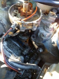
The distributor is STUCK in there. I have tried everything I can think of to get it out. It had what looked like a decade and a half of grime all around teh base, I couldn't even tell what it was supposed to look like... had to find pictures online lol...
anyway I got it as cleaned up as I could, reomved the retaining bolt & bracket...
I have it at DTC (or at least pretty close, the damper timing marks are too faded to read). I have tried wiggling it, twisting while pulling upwards, very gently using a prybar... even giving it a few love taps w/ a steel bar and hammer... no movement at all, it acts like its welded in...

Added fun: In trying to get it loosten it, I was gently prying on it w/ a prybar and the plastic round body seems to have broken off from teh shaft, so that part wiggles now....

Any suggestions?
 

Attachments

  • IMG_20140705_164000.jpg
    IMG_20140705_164000.jpg
    165.1 KB · Views: 247
Hose it down with wd40, pb blaster, kroil etc. Keep tapping. Sometimes u can chisel it sideways. If u can make it turn then it'll be easier to get out. Spray it let it soak and keep trying
 
Should it be able to turn sideways with the teeth meshed etc? Shouldn't it have to go up and turn together?

Oh right there should be a little rotation for timing adjustment.

I'll give it some more profanity then. Thanks.
 
Yep with that vacuum canister off of it it should be able to turn 360*. Yep more cussing should fix it. Id clean the hole in the block with sandpaper carefully and put some anti seize on it so it'll come back apart in the future
 
I find profanity really helps. At least it makes me feel better.
But, it also relegates me to only working after the kids are in bed!
 
Got it out. Needed more profanity.

Got a new matching distributor.
Cannot get the damn thing to slide all the way back in :sniper:.
With a little wiggling, it will drop down past the gear so teh rotor is locked in place, however it just stops with ~1/4" to go. Can still see the sealing ring popping up.
I'm really wondering about that damn oil pump shaft that sticks up, looks liek it has a hex head on top so it goes into a hex key on the bottom of the distributor.
the shaft is a little loose a floppy sticking up down in the hole... dosn't look like it's sitting right in the center of the hole, instead it can wobble around. Is that normal? I feel like maybe the pump shaft isn't quite lined up and is preventing the dizzy from sliding all the way down...
 
i never use timing marks so this may not be good for you. if your sure the gear is meshed with the cam, have someone bump the starter a few times while you wiggle the dizzy, it will usually drop right in.
If you don't want to try this tape a 1/4" socket to an extension so it can't fall off mysteriously and slightly turn the oil pump shaft. Retry the distributor and repeat til it drops in. Sometimes it helps if you wiggle the dizzy base and the rotor button simultaneously. The oil pump shaft is slightly tapered so if its not quite centered it'll still line up with some wiggling.

The starter bump thing works great too but if you have to backup and pull the dizzy out of mesh you'll have to know how to find tdc and get it back in time from scratch which is harder for a first timer than lining up marks. If it comes to that we can walk you through that procedure also.
 
Oh, the ship has already sailed on keeping it aligned w/o having to re-find TDC. I tried using the starter-bump method to help wiggle it in w/o any luck. FYI it's super easy to do by yourself on this truck b/c the solenoid is right there mounted on the D-side fender, all it takes is an alligator clip touched to the battery.
So, yeah, I'm going to have to re-find TDC... what makes it really fun is that the marks are not readable on the crank pulley, have only the one big notch... and the space between the pulley and radiator is so tight, I can't really get a ratchet in there to turn the pulley by hand. So I'm stuck w/ teh starter-bump method... guess I have to find it by predicting when #1 is at full height?
 
Lightly sand the balancer. That'll usually show the marks. Lay underneath and sand all you can see. Bump it over and sand til you find them. Then put a dab of paint on the mark you want the timing at. You'll need timing marks to time it with a light after the distributor drops in anyway. Once you find the marks just pull number 1 plug and bump engine till you feel compression when your finger is over the plug hole. That way you'll know you're at tdc compression not exhaust.
 
Well got it all back together. Ended up having to take the crank pulley off and examine it very closely to find teh original marks... I ground a couple of lines in it @ -10, 0, 10 for future reference (and repainted to look nicer).
Low and behold after a little bit of wiggling, got the dizzy back in - its funny it was hard the first time, but after that each time I had to pull it out (to line up rotor etc) went in pretty easy. Lines up w/ TDC etc.

And yet... I still have no spark. I have confirmed the resistance on teh inductor coming out of the dizzy is in range. Have confirmed that teh 2 wires going to teh coil are in range (when key ON), at the coil connector there is 12V coming in from reddish wire (from ignition and tied to DS module), and a little lower (10ish) on the green wire coming from the DS box.
I even got a new DS module, thinking maybe it wasn't pulsing correctly.
Only thing left that hasn't been replaced in the coil. I measure 1.62 Ohms across the two leads (primary?), and ~9,830 between the output wire going to dizzy cap and either of the contacts.
I'm finding some conflicting info online re: specs for the primary (some say 1-2, others 0.3 & 1.0. Any insight? to me this difference is very small but I guess it dosn't take much. I guess I could try replacing the coil just to see....
...at this point I'm seriously considering returning the placement Duraspark module and going for the GM HEI conversion... would only need a coil and module...
 
IGNITION COIL PRIMARY CIRCUIT SWITCHING CHECK

  1. Disconnect ignition module 3-wire connector and install diagnostic adapter (T79P-12127-A or equivalent). Connect a test light between "TACH" terminal of ignition coil and an engine ground. With ignition switch in "RUN" position, touch diagnostic adapter test lead to positive battery terminal.
  2. Test light should flash each time test lead is either connected to or removed from battery terminal. Turn ignition switch "OFF", remove diagnostic adapter, and reconnect ignition module wires.
  3. If test light flashes, proceed to "Ignition Coil Secondary Resistance Check". If test light does not flash or is dim, proceed to "Voltage Supply Circuits Check".
IGNITION COIL PRIMARY RESISTANCE CHECK [ IGNITION SYSTEM - DURA-SPARK III : TESTING ]

  1. Disconnect ignition coil connector. Connect ohmmeter leads to "BATT" and "TACH" terminals of ignition coil. Measure resistance, remove ohmmeter leads, and reconnect ignition coil connector.
  2. If resistance was 0.8-1.6 ohms, proceed to "Module-to-Coil Wire Voltage Check". If resistance was less than 0.8 ohm or greater than 1.6 ohms replace ignition coil.
IGNITION COIL PRIMARY RESISTANCE CHECK [ IGNITION SYSTEM - DURA-SPARK II : TESTING ]

  1. Disconnect ignition coil connector. Connect ohmmeter leads to "BATT" and "TACH" terminals of ignition coil. Measure resistance, and reconnect ignition coil connector.
  2. If resistance is 0.8-1.6 ohms, coil is OK. Proceed to "Primary Circuit Continuity Check". If resistance is less than 0.8 or greater than 1.6 ohms, replace ignition coil.
IGNITION COIL SECONDARY RESISTANCE CHECK [ IGNITION SYSTEM - DURA-SPARK II : TESTING ]

  1. Disconnect ignition coil secondary wire and ignition coil connector from coil. Connect ohmmeter leads to ignition coil "BATT" terminal and to high voltage terminal. Measure resistance and reconnect wire and connector.
  2. If resistance is 7700-10,500 ohms, coil is OK, proceed to "Module-to-Coil Wire Check". If resistance is less than 7700 or greater than 10,500 ohms, replace ignition coil.
IGNITION COIL SECONDARY RESISTANCE CHECK [ IGNITION SYSTEM - DURA-SPARK III : TESTING ]

  1. Disconnect ignition coil connector and secondary wire from ignition coil. Connect ohmmeter leads to "TACH" and secondary terminals of ignition coil. Measure resistance, remove ohmmeter leads, and reconnect coil wires.
  2. If resistance was 7700-10,500 ohms, coil is OK. Measure resistance of ignition coil-to-distributor wire.
  3. If wire resistance is greater than 5000 ohms per inch, replace ignition coil wire and proceed to "Ignition Coil Primary Resistance Check". If coil resistance is less than 7000 ohms or greater than 10,500 ohms, replace ignition coil.
IGNITION COIL VOLTAGE SUPPLY CHECK [ IGNITION SYSTEM - DURA-SPARK III : TESTING ]

  1. Attach negative lead of voltmeter to engine ground, and positive lead of voltmeter to "BATT" terminal of ignition coil. Turn ignition switch to "RUN" position and measure voltage. Turn ignition switch "OFF".
  2. If voltage was 6-8 volts, proceed to "Module-to-Coil Wire Resistance Check". If voltage was less than 6 volts or greater than 8 volts, proceed to "Ignition Coil Primary Resistance Check".
IGNITION COIL VOLTAGE SUPPLY CHECK [ IGNITION SYSTEM - DURA-SPARK II : TESTING ]

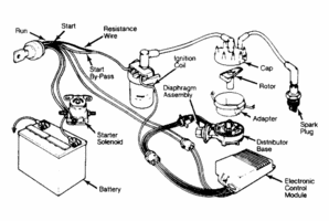
  1. Connect negative lead of voltmeter to distributor base and positive lead to "BATT" terminal of ignition coil. See Figure. Turn ignition switch to "RUN" position, and read voltmeter. Turn ignition switch "OFF".
  2. If voltage was 6-8 volts, proceed to "Pick-Up Coil & Distributor Wiring Harness Check". If voltage was less than 6 volts or more than 8 volts, proceed to "Ignition Coil Primary Resistance Check".
IGNITION COIL

COIL RESISTANCE (Ohms)
PrimarySecondary
0.8-1.67700-10,500


168638-c29a5d3fdc75ce9ab76d30b8abd23c1d.jpg
 

Attachments

  • bronco.gif
    bronco.gif
    65.5 KB · Views: 222
So 1.6 is the limit... guess I'm over? will try a swap.
That HEI conversion is looking better and better...
 
Coils are tricky. I've seen them test OK and not fire and I've seen them fail the resistance test but fire. They'll get hot and start breaking down under load. As cheap as it is I'd replace it. Make sure you get one for duraspark if you decide to keep the module. If the resistance isn't right it'll pop a duraspark box. The same coil will work if you swap to a gm module later.
 
Yup, coil.
Picked up a universal Accel and swapped it, have spark now.
At this point I think I'm going to return the new DS2 module and the Accel coil, and just change over to the HEI module and a newer style TFI coil, might as well be a little more current.
Do I correctly understand that w/ the TFI solid coils you don't need a ballast/resistor wire?
Yea you don't need a resistor if you use the gm module but unless its got an aftermarket ceramic block resistor tack in the wiring you'll have to run a new wire. The factory resistor on a ford is a resistance wire. It'll be the actual wire taped into the harness.
 
If I do convert, I'm ditching all the wiring and starting fresh. Not like there's much to it w/ the HEI setup.
Biggest PITA is having to scrounge up a pigtail for a TFI coil and to connect into the Duraspark orange/purple/black wire plug off the distributor (from the stator). That one I could just cut off and make my own connector, but I don't like hacking factory connectors if its avoidable.
 
Back
Top