D-6

I've decided to use a Procharger style supercharger on the D-6. 950 horsepower in a configuration I feel more comfortable building around, and doesn't create a blind spot for the driver which was a big deal for me from the start. Gonna be super fun to let that 6 speed transmission eat. Air-to-Air Intercooler for Procharged intake, bumpstops, tie rods, and a little further with the chassis tubing. I have the knuckle turning almost 35 degrees now, but I'm not going to lock it down until I figure out if I need to back it off 3.5 degrees to 31.5 because I have 7 degrees of caster.

133608998_1808971729278018_5689395591581466584_o.jpg


134484501_1807747716067086_6620617776067246868_n.jpg


steering 4.jpg


D-6 1.jpg


D-6 2.jpg


D-6 3.jpg


D-6 4.jpg


D-6 5.jpg


D-6 6.jpg
 
Last edited:
Reconfigured more of the tubing with thinning of the belly, and worked in some replaceable rock armor. Will be a down tube (or two) attached to the center of the belly, but won't get there until the rear suspension is complete.

D-6 11.jpg


D-6 12.jpg


D-6 13.jpg


D-6 14.jpg


D-6 15.jpg


D-6 16.jpg


D-6 17.jpg


D-6 18.jpg
 
I've decided to refrain from trying to take the rear suspension to another level. Maybe one day. Right now, I think it's probably a good idea to dissect a regular 4 link style rear end. So, I'm going to open up about it, and try to get as much travel from the rear end as I can without having to change the transmission out. So, in other words I'm going to address the anti-squat, the roll axis, shock placement, and the drive shaft plunge using the Bomber 6 speed setup along with the 4 speed atlas. All of the tubing rear of the B-pillar is subject to change.

rear suspension 1.jpg
 
This is what the new 4 link geometry for the rear end looks like. The blue line represents the roll axis. I located the instant center just above the front differential. The drive shaft plunge is less than 2 inches, and the rear wheel travel is 31.75 inches. I set the anti-squat value to 100% which basically means that the rear of the chassis won't unnecessarily squat, or lift up in the air under acceleration. To explain that further, it means once the coil-over spring recovers from the initial compression from acceleration, the suspension is going to recover back to a static ride height style stance while gaining speed.

roll axis 2.jpg


roll axis 3.jpg


roll axis 4.jpg


roll axis 5.jpg


roll axis 6.jpg


roll axis 7.jpg


roll axis 8.jpg
 
This is what the new rear suspension looks like with shocks on it. 16 inch coil-over, and a 20 inch bypass shock. Just under 32 inches of rear wheel travel. It should articulate well, and track straight too.

rear suspension 5.jpg


rear suspension 6.jpg


rear suspension 7.jpg


rear suspension 8.jpg


rear suspension 9.jpg


rear suspension 10.jpg


rear suspension 11.jpg


rear suspension 12.jpg


rear suspension 13.jpg


rear suspension 14.jpg


rear suspension 15.jpg


rear suspension 16.jpg


rear suspension 17.jpg


rear suspension 18.jpg
 
That's cool, now why can't you also have a different motion ration on the front LCA (coilover and bypass damper) to fix the packaging problems and stop loading the LCA in torsion? ;)

Make sure that lower link is really strong/stiff in bending, because all of your rear suspension loads into the coilover and bypass damper are putting that lower link in bending (like a longer version of a front LCA).

I feel like jumping into the lower control arm again is warranted now that the knuckle is visual. Some of the guys in the industry lately have been milling out aluminum trailing arms on their rear suspension. I'm leaning toward chromoly plate trailing arms, but I haven't made a decision yet. Probably going to boil down to which one is lighter.

Don't forget, I'll put air bumps above the rear end housing also.
 
How does aving the spare tire angled on the back like that affects rear suspesnion performance? I know its a common design now. That's a non trivial amount of weight, and the farther it goes from your link point the more leverage it has.
Is it actually actually good to have to keep the suspeension a little loaded, and more balanced against the front so it's less stiff?

I suppose if it didn't need much fuel volume on the car I could squeeze the spare tire in between the b-pillar, leaned back above the transfer case. The center of the car would probably be the optimum place to put it, but the fuel cell and the radiator placement will prevent me from doing that.

I guess placing it after that boils down to keeping center gravity as low as it can be attained. I'd rather have the fuel cell towards the center of the car. With it being in the center the weight change as it loses fuel is going to affect the whole car rather than just the rear end. Resulting in a more consistent suspension tune as the fuel cell drains. So for example if the fuel cell was hanging off the back of the car behind the axle, it would have a more drastic effect on the suspension tune when it drained weight from the rear of the car.

Later on down the road I'm sure it will have a separate spring rate and tune for "tire on" and "tire off". Probably a few tunes for each cause I know I'll never be satisfied enough to stop tinkering with it.
 
Take the 90 deg bend out of the ends of those long pieces of tubing on the tire mount; that's a bucking point if you feed axial (tension/compression) loads into those pieces of tubing. I know that entire cage section is only supporting the spare tire, but you might as well make sure it can also serve duty as additional rollover protection. The length of that tube is not tied to anything laterally either (in the middle), but again it all depends if that is going to remain as just mounting support for the spare tire.
 
Last edited:
Take the 90 deg bend out of the ends of those long pieces of tubing on the tire mount; that's a bucking point if you feed axial (tension/compression) loads into those pieces of tubing. I know that entire cage section is only supporting the spare tire, but you might as well make sure it can also serve duty as additional rollover protection. The length of that tube is not tied to anything laterally either (in the middle), but again it all depends if that is going to remain as just mounting support for the spare tire.

I'll be completely honest, I don't know what the back half will look like when it's done. That was the first solid look at the back half with shocks on it. The rear end would twist or tear the tail off the car like it is at the moment. Right now I'm debating how much I want to protect the side of the shocks. I suppose right now I should mount the air bumps, and move forward from there. A lot of emphasis is about to put into chassis detail from here on out.
 
Hmmm.

100% static Antisquat, and by the images, you will have substantially more in droop.
20” bypasses with that much wheel travel, regardless of the motion ratio, should be some interesting piston speeds.

hows the angle where the driveshaft meets the case in droop?

how about the angles of the misalignments on the heims/uniballs when it articulates with that much travel and trailing arms?

this will be extremely “interesting” to watch... especially on sand, dirt, whoops, etc. I don’t want to watch it try to climb a waterfall obstacle, wet or dry.

J.E. Reel sent word last week that I could achieve 37 degrees at the transfer case. I have it set at 35. The misalignment angle your asking about looks like the uni-ball at the chassis, and the uni-ball at the axle will have to split the responsibility of 28 degrees.
 
J.E. Reel sent word last week that I could achieve 37 degrees at the transfer case. I have it set at 35. The misalignment angle your asking about looks like the uni-ball at the chassis, and the uni-ball at the axle will have to split the responsibility of 28 degrees.
But when you use them on trailing arm, you want the arm to stay parallel to the shock shaft. This constrains the link and forces the misalignment to happen at the axle end during articulation.

no comment on the geometry?
 
But when you use them on trailing arm, you want the arm to stay parallel to the shock shaft. This constrains the link and forces the misalignment to happen at the axle end during articulation.

no comment on the geometry?

Sure, the anti-squat will raise in percentage as the tire drops out. Not unlike anything else, although it should be great for climbing. The lower shock uniball is located a quarter inch below the center line of the trailing arm. The spring tension pushing down on the trailing arm will keep it parallel. Even in the occurrence of the lower trailing arm binding up on itself the lower shock uniball will have plenty of angle movement to do its thing. So just to recap in short, I don't see it binding up.
 
Sure, the anti-squat will raise in percentage as the tire drops out. Not unlike anything else, although it should be great for climbing. The lower shock uniball is located a quarter inch below the center line of the trailing arm. The spring tension pushing down on the trailing arm will keep it parallel. Even in the occurrence of the lower trailing arm binding up on itself the lower shock uniball will have plenty of angle movement to do its thing. So just to recap in short, I don't see it binding up.
Increase in anti squat in droop is not a good quality, especially not when you start with as much as your design has.

I expect to see massive rear wheel hop in deep sand and while climbing more vertical obstacles.

I’m guessing you haven’t plugged your data in the newest calculator and analyze.

So your 28° misalignments at the rear axle is enough for 32” travel? At what horizontal separation are your lower links mounted to the rear axle?
Is that 28° each direction or 28° misalignment total?
Asking bc those numbers base on 32” travel don’t trig well compared to your misalignments.

let’s say it’s 28° each direction, tan28 = .571, 32” travel divided by .571 equals 60” + horizontal separation between uniballs where they attach to the axle.
If it’s 28° total misalignment,

That’s tan14= .249, with links mounting on axle 50” apart thats 12.5” inches of vertical wheel travel(articulation) before bind.

but I’m sure no need to use trig, just cycle it in your cad software, and what’s the angle difference between the rear housing and the chassis belly at full articulation.

or

set a constraint to the rotation of the uniball misalignment and then measure what travel you can achieve before the t-arm binds and bends/breaks the shock shaft.
 
Last edited:
Increase in anti squat in droop is not a good quality, especially not when you start with as much as your design has.

I expect to see massive rear wheel hop in deep sand and while climbing more vertical obstacles.

I’m guessing you haven’t plugged your data in the newest calculator and analyze.

So your 28° misalignments at the rear axle is enough for 32” travel? At what horizontal separation are your lower links mounted to the rear axle?
Is that 28° each direction or 28° misalignment total?
Asking bc those numbers base on 32” travel don’t trig well compared to your misalignments.

let’s say it’s 28° each direction, tan28 = .571, 32” travel divided by .571 equals 60” + horizontal separation between uniballs where they attach to the axle.
If it’s 28° total misalignment,

That’s tan14= .249, with links mounting on axle 50” apart thats 12.5” inches of vertical wheel travel(articulation) before bind.

but I’m sure no need to use trig, just cycle it in your cad software, and what’s the angle difference between the rear housing and the chassis belly at full articulation.

or

set a constraint to the rotation of the uniball misalignment and then measure what travel you can achieve before the t-arm binds and bends/breaks the shock shaft.

I don't know. Maybe I'll just turn the shock bolts parallel with the trailing arm and get rid of the entire issue all together. I already know that I'm going to turn the bolts on the top side 90° from where they're at now.
 
I don't know. Maybe I'll just turn the shock bolts parallel with the trailing arm and get rid of the entire issue all together. I already know that I'm going to turn the bolts on the top side 90° from where they're at now.

still you haven’t addressed :

-the massive AS and it’s impact on vehicle handling and dynamics

- over traveling what the uniballs allow during articulation

- bypass piston speed and handling quirks

- massive about of suspension geometry deviation from static thru travel

Maybe it was better off when the rear was “classified”.

Have you thought about a cantilever setup? :flipoff2:

I see. I'll get back with you later
 
still you haven’t addressed :

-the massive AS and it’s impact on vehicle handling and dynamics

- over traveling what the uniballs allow during articulation

- bypass piston speed and handling quirks

- massive about of suspension geometry deviation from static thru travel

Maybe it was better off when the rear was “classified”.

Have you thought about a cantilever setup? :flipoff2:
its a make believe build, you should have learned by now to just sit and watch lol
 
still you haven’t addressed :

-the massive AS and it’s impact on vehicle handling and dynamics

- over traveling what the uniballs allow during articulation

- bypass piston speed and handling quirks

- massive about of suspension geometry deviation from static thru travel

Maybe it was better off when the rear was “classified”.

Have you thought about a cantilever setup? :flipoff2:

Alright, so lets get into it. Lets assume the blue line is where my instant center travels. A little background information for those who don't know. The instant center is the imaginary point from the side view where the upper and lower rear links connect towards the front of the vehicle. The instant center is where the force is applied to the car, from the rear end pushing the car forward. The idea is to push through the heavy weight of the vehicle. Now, at the moment we are all getting the first glimpse of what the fuel cell may look like. Right now, it's 45 gallons. The volume could go up or down. Forgive me if I get a little bit elementary with some of this, but that's how I like to do things. The number one thing I'd like to point out is this is not a trophy truck. It is an Ultra 4 car. A trophy truck, and an ultra 4 car are completely different animals. One crawls over rocks, and the other one doesn't, I think you can make the assumption. Alright, so now, we immediately run into having to design around crawling over, and half way around huge boulders. Articulation, and wheel travel is what you need to accomplish this successfully. The more of both you have, the better chance you have of completing a rock trail without help. To accomplish this at speed is going to take a good car, and a good driver.

Alright, so lets answer some of these questions. One of the questions that was asked was about the massive anti-squat, and it's impact on the vehicle handling and dynamics. In my opinion, anti-squat is one of those things few people even talk about, or know anything about. The reason behind this is they never get far enough into the design of their car to actually give a shit about it. It's just one of those things that most will look at like 'Eh yeah, I don't know what that is, and I don't care. <----- This particular thought is what is what I see when I examine most rock bouncers. Because, there again. No body know's, or give a shit. What you actually run into is a mixing problem that occurs when these guys try to make a go fast vehicle basing is it off what they see originating from desert racers. You can click on google photo of a trophy truck right now, and bask in the glory they behold carrying those big ass parallel lower trailing arms. What those big ass parallel lower trailer arms actually do is substantially raise the roll axis to a degree that would astound you. That's what all your guys in the rock crawler industry are starting to put on their rigs because they are following these west coast guys in the go fast industry, and trying to copy their shit. Now, how do you mix this anti-squat figure with your roll axis? Well, you have to move the front joint on the trailing arm towards the inside of the vehicle. It lowers the roll axis in a traditional 4 link, keeping the chassis in a more flattened relation with the earth looking at it from an articulation stand point.

K, so the next question about my car that consists of over traveling the uniballs from the chassis to the axle. I'm under the impression I can get 60 degrees with high misalignment spacers combining two separate uni-balls. Will I have to factor this rotation in with the lower joint on my rear shocks? With out a doubt, Yes. Will I exceed the limits of my trailing arm's movement with articulation? No, not with proper mounting of the link mounts, and orientation of the uni-ball.

Lets move on to bypass piston speed. What you run into with piston speed inside the shock body is pressure. I've never had to answer a question like this, but the answer is pressure. The faster the piston moves up the shock body, the more pressure it creates on the everything inside while it's trying to make it's way up through the oil. The piston inside of the coil-over is gonna have to push it's way through every ounce of fluid contained inside the shock body. Maybe some of you guys have seen an emulsion coil-over explode? This is the reasoning behind whatever busted. The piston moving from the bottom of the shock body to the top created so much pressure, and the piston was moving so fast to the point where the components of the shock body couldn't contain the pressure any longer, it exploded. This is why remote reservoir shocks where invented. A nitrogen charged empty cavity tube with a separate piston dividing the oil from the nitrogen was introduced. It allowed the piston speed to move faster while only moving a certain amount of oil pressure though the piston valving. In other words, the remote reservoir takes the blow. Alright, so lets relate this to the bypass shock. The remote reservoir bypass shock doubles this feature, and give your more control. Now we have created tunnels for the oil to bypass ( go around ) the piston. We can restrict this fluid bypass where we want through out shock travel. All this allows for reliable, and complete control of your suspension. I would think there needs to be a solid understanding out there that what you need to do is, demand the bypass shock to control the movement of your wheel travel, and ask the coil-over for help when you need it. A good suspension guy will start there to see what's going on with your suspension. A great suspension guy is going to start by looking at your spring rate.

The last question that was asked, was about the massive geometry deviation through static travel. As far as I'm concerned, it flows through the heart of my car, and doesn't deviate. If this thing is ever asked to conquer 80 degree ledges, it can do it with the burden of responsibility handed off to the driver.

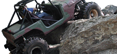
I'd like everyone to take a decent look at the last photo, and ask yourself where the center of gravity might be in relation to where the rear end is pushing.

rear suspension 24.jpg


rear suspension 25.jpg


rear suspension 26.jpg


rear suspension 27.jpg


rear suspension 28.jpg


rear suspension 29.jpg
 
First look at the centralized fuel cell. 45 gallons. I'm on track to change some of the characteristics of the fuel cell layout, but I need to read the rule book on tube structure before I can move forward with it.

D-6 21.jpg


D-6 22.jpg


D-6 23.jpg


D-6 24.jpg


D-6 25.jpg


D-6 26.jpg


D-6 27.jpg


D-6 28.jpg


D-6 29.jpg


D-6 30.jpg


D-6 31.jpg
 
Blah, and more Blah.

If this rig had a flux capacitor and would reach 88mph in the "i'm tripping on acid" movie, it would be BADASS!
 
Blah, and more Blah.

If this rig had a flux capacitor and would reach 88mph in the "i'm tripping on acid" movie, it would be BADASS!

Well, at least Scott is making some sort of contrubution to moving forward. I don't know what it is your doing.
 
Back
Top