D-6

I think the packaging around the CV doesn't matter at all, because you're not going to have enough steer angle with the monoball in that orientation. Might be marginal at normal ride height, but then you have compound angles in bump and droop that might not get you where you want to be. I'm going to play the "there is a reason why front ball joints are oriented like that" card. ;)

Why is tapping not an option? That's pretty common to do for a steered upright like that, with a retaining tab/plate/bracket whatever to capture the bolt head to prevent it from turning and falling out. Make sure that whatever orientation you use that the monoball is mounted in double-shear, which is normally just a machined pocket to capture the monoball on both sides. I'm not sure if you need as tall of a misaligntment stack as you think you need, depending on what type of clearance you have around the monoball.

I'll get back to you @Fabrik8
 
Other than the Misalignment spacers, I almost made the mistake of believing all these parts were interchangeable. I was under the impression I could run that trophy truck cup with the $60 to $80 dollar uni-balls. I don't really think I need to be running $300 to $500 dollar uni-balls. If I want to run the $60 to $80 dollar uni-balls, the inside bore on the trophy truck cup is too deep. Luckily, I don't have to change the cup measurements on the drawing, but it looks like I'll be running the 3-1/2" OD cup with the thinner bore. Part Number - KTK9046HD This is the cup I have to run for the $60 to $80 dollar uni-balls.

Alright, so back to attempting to rotate the outboard control arm bearings. I guess I was conceptually thinking I needed to run a misalignment spacer with a wide head diameter to prevent them from chewing up the mounting surface. This is probably not the case. As of right now, I am looking into a misalignment spacer with a 3-1/2 inch stack height.

I'm gonna try to rotate the outboard uni-ball cups somewhat horizontal with the earth. The extreme angle is 28.75 degrees on that lower outboard joint at droop. If I can get it to work, I'll probably end up changing the misalignment stack height to 3.5 inches throughout the entire car.

InkedScreenshot 2020-11-28 190650_LI.jpg


InkedInkedScreenshot 2020-11-28 191952_LI.jpg


InkedScreenshot 2020-11-28 192252_LI.jpg


Screenshot 2020-11-28 193339.jpg


Screenshot 2020-11-28 193703.jpg


Screenshot 2020-11-28 193426.jpg


Screenshot 2020-11-28 193512.jpg
 
I'm gonna try to rotate the outboard uni-ball cups somewhat horizontal with the earth. The extreme angle is 28.75 degrees on that lower outboard joint at droop. If I can get it to work, I'll probably end up changing the misalignment stack height to 3.5 inches throughout the entire car.

Yeah, put a angle jog in the control arm if necessary to get the proper monoball angle at normal ride height, assuming you've got equal amounts of travel in bump and in droop.

Here's an example of a few types of double shear mounting in a front position; this is apparently for a UTV (something I just found quickly on Google) but it shows the concept of making a double-shear pocket for the monoball. This upright uses nuts for the shear bolts, but it's just as common to use a tapped hole and a capture plate for the bolt head instead. The bottom mount usually takes the most force, which is why it's the beefiest (the LCA usually has more applied force from the wheel than the UCA because of things like damper forces, and usually a shorter distance from the LBJ to the hub axis). There are generally bending forces along with tension/compression on the LCA, instead of just tension/compression forces on the UCA (again, assuming the spring/damper is mounted to the LCA). This is why you will often see a larger monoball at the bottom than at the top, to save weight by downsizing the lighter-loaded upper joint.
You can do similar things with a fabricated upright instead of a machined upright; the concepts are the same.

Fortin-Product-Profile-Photos_All_CAN-AM_X3_Front-Hub_5.jpg
 
Last edited:
6011357967629aa86c2853436217899b.jpg


be22bb0c3a6ddab2f7f031e9fdc5b00f.jpg


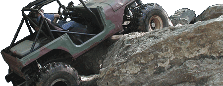
Portal IFS uprights. From same companies mentioned above, who also sell bulkheads, and can also provide a-arms...


Nice, those are slick. From the looks of those claw marks, it appears like they were able to accomplish the process using a 3-axis mill. That's good news. Although, on mine I don't plan to bore out all that meat in the bolt holes.
 
Looks simple now that it's done. :lol: 
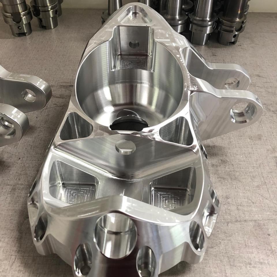
I guess one could argue that I've either spent 2 weeks, or 6 months on this lower control arm. I know Dan Dubose isn't going to want any of this Motobilt stuff coming off his laser machine looking like cheese factory. I feel like I put a lot of effort into it, and you guys helped make it. Thanks.

lower control arm 31.jpg


lower control arm 32.jpg


lower control arm 33.jpg


lower control arm 34.jpg


lower control arm 35.jpg


lower control arm 36.jpg


lower control arm 37.jpg


lower control arm 38.jpg
 
Last edited:
I would recommend either not cutting out these windows, or at least making them an X or other triagular based form. The amount you have weakened it is exponentially greater than the weight you are saving.
upload_2020-12-11_8-37-32.png
 
I’m no train driver, but you are missing some material where the amount of greatest load is cantilevered. I foresee bent control arms in the future.

Revision needed or push the rear LCA rear some more to eliminate the cantilevered load.

Your material need in that plane stops at the first shock mount. This combined with HAZ from assembly is a poor recipe.
 
I would recommend either not cutting out these windows, or at least making them an X or other triagular based form. The amount you have weakened it is exponentially greater than the weight you are saving.
View attachment 332828

Maybe I'll replace the columns in those windows with hollow rotated squares.

I’m no train driver, but you are missing some material where the amount of greatest load is cantilevered. I foresee bent control arms in the future.

Revision needed or push the rear LCA rear some more to eliminate the cantilevered load.

Your material need in that plane stops at the first shock mount. This combined with HAZ from assembly is a poor recipe.

Yeah, I could see the control arm twisting if the bump impact made it to the shock, but the shocks will never collide with the control arm. I feel good about the interlocking runners that make their way to the outer joint. When they are welded together and essentially connected to the upper and lower plates, everything should be plenty strong enough to handle the spring tension without twisting. Once I administer the bump stop location on top of the knuckle, it's going to negate the collision with the shock, and the potential twist.
 
Maybe I'll replace the columns in those windows with hollow rotated squares.
That would be a major improvement. If it were me, I'd also move the windows away from the weld joints a good bit more. Maybe do 2 larger windows instead of 4. But I also don't think the weight savings is worth it in that area and would just leave it solid.
 
Shoot, crucial things I have to go over. I almost forgot to integrate a hole or two in the control arm to lift a flat tire off the ground with a jack. This particular screw jack requires the use of 3/4 inch socket.

Maybe there are some mechanics on here that can recommend the right battery powered impact gun to outfit on the car. I'll have to plan on mounting this jack, and the impact on the car so the driver will be prepared to pull off the track and change a flat tire.

I'm not sure if I like the fact that the nut on this Jack requires a 3/4 inch socket. I'd like to use the same socket to change the wheel and operate the screw Jack. Maybe I can take it apart and modify the screw to make it use a larger hex.

I wonder how many tires one of those nice 1/2 inch battery impacts can change on one charge and jack the car up a number of times.

Screenshot_20201211-165148.png
 
I see a weld tab with nothing underneath it. Need to change the pockets there, or move/delete the weld tab. Minor detail though, and easy to fix.

There's some other causes for concern for buckling as well, but this is not my project. I like the "torsion box" concept for the control arm though, kinda fun.

Also, what is the purpose of the long pocketed strip that's along the side at an angle? Is that to zip-tie hoses to or something?
 
Last edited:
Shoot, crucial things I have to go over. I almost forgot to integrate a hole or two in the control arm to lift a flat tire off the ground with a jack. This particular screw jack requires the use of 3/4 inch socket.

Maybe there are some mechanics on here that can recommend the right battery powered impact gun to outfit on the car. I'll have to plan on mounting this jack, and the impact on the car so the driver will be prepared to pull off the track and change a flat tire.

I'm not sure if I like the fact that the nut on this Jack requires a 3/4 inch socket. I'd like to use the same socket to change the wheel and operate the screw Jack. Maybe I can take it apart and modify the screw to make it use a larger hex.

I wonder how many tires one of those nice 1/2 inch battery impacts can change on one charge and jack the car up a number of times.

View attachment 332862
A Milwaukee M18 fuel compact impact with 12.0 battery could probably do it 500 times.
 
Did I lead you guys into thinking that there's no top or bottom to the control arm? Sorry about that, haha. I was pretty tired last night when I posted those pictures. At the time I was thinking I should probably elaborate more, but I didn't. My mistake.

There is an 1/8 inch thick ceiling to that control arm, and a 3/16 thick floor. I was just trying to show you the internals.

The bent weld tab you're referring to with nothing under it is axle recess. The ladder looking pieces in the front will get stitch welded to the floor, and the front of the control arm to help keep the lower outside fillet weld in tact when rocks take a dent lick on that lower front weld.
 
The bent weld tab you're referring to with nothing under it is axle recess.

Nope, not that one. The one in front of that.

Also, you should put a radius at the "V" between the two inboard legs, even if it's just a generous fillet in the top and bottom skin and not the bent plate pieces.. Else, the skins are going to crack there.
 
Last edited:
That piece has the sole purpose of keeping the floor from acquiring a huge dent in the bottom of it, but it doubles as reinforcement for the front.

Okay, makes sense. I'd still move the weld tabs to the left and right of the unsupported area on top. If you're going to have a weld tab, make it do work. Else you're just adding a buckling point. Remember that if you're stressing the skin of the control arm to make a torsion box, you don't want to add unnecessary features that could add local stress.
You're doing a cool design, it just needs to be thought through a little more.
 
Last edited:
Nope, not that one. The one in front of that.

Also, you should put a radius at the "V" between the two inboard legs, even if it's just a generous fillet in the top and bottom skin and not the bent plate pieces.. Else, the skins are going to crack there.

Okay, makes sense. I'd still move the weld tabs to the left and right of the unsupported area on top. If you're going to have a weld tab, make it do work. Else you're just adding a buckling point. Remember that if you're stressing the skin of the control arm to make a torsion box, you don't want to add unnecessary features that could add local stress.
You're doing a cool design, it just needs to be thought through a little more.

So I feel like what your trying to get across is I need to get rid of these centrally stationed weld tabs, and make some on the east and west sides of it. Then I need to make sure I gusset both interlocking intersections.

lower control arm 40.jpg
 
So I feel like what your trying to get across is I need to get rid of these centrally stationed weld tabs, and make some on the east and west sides of it. Then I need to make sure I gusset both interlocking intersections.

View attachment 332896

The highlighted one closest to the viewer is the one that needs to be tweaked. If you visualize the load paths based on the pockets in the plate, putting a weld tab on either side (instead of the middle) makes sense. Think about it like the nodes of a truss.

The other one you have highlighted looks fine. It's sort-of the inverted version of the first one, so a tab in the middle makes sense for load paths, because the tab is at the node.

I don't want to hyper-focus on that one small detail, it was just something that jumped out at me.
 
Last edited:
The highlighted one closest to the viewer is the one that needs to be tweaked. If you visualize the load paths based on the pockets in the plate, putting a weld tab on either side (instead of the middle) makes sense. Think about it like the nodes of a truss.

The other one you have highlighted looks fine. It's sort-of the inverted version of the first one, so a tab in the middle makes sense for load paths, because the tab is at the node.

I don't want to hyper-focus on that one small detail, it was just something that jumped out at me.

Hyper-focus if you like. I was just not aware of your keen depth perception. I understand your point now. I was taught that is referred to as the "flow of continuity." I'm about a plus or minus, average talker anyway. I enjoy how you can process your thoughts, and get them out with normal words. I don't mind anyone getting picky with the drawing.

Seems overkill. How much torque is required for this jack?

I don't know how much torque is required to operate the jack. The gun will carry a big responsibility though.
 
A couple sweet improvements. :rockon:Now onto introducing a tube hole for the jack, and forming the gussets that we're after to ensure we knock out this twisting concern.

lower control arm 41.jpg


lower control arm 42.jpg


lower control arm 43.jpg


lower control arm 44.jpg


lower control arm 45.jpg


lower control arm 46.jpg
 
Back
Top