Legends Class 4800 Build - “Tinkerita”

Do you feel like the wobble stopper in the trailing arm limits travel more than say a heim at both ends with delrin bushings on the shock eyes? How important is the axle heim in the equation with the wobble stopper up top? Would a 1" heim with a 1" bolt get bound up? Is that high misalignment spacer the key to the whole deal?
Not to high jack their thread, but no its not limiting travel for the short answer. Its still traveling 4ish degrees on each side at the wobble stop if its a tmr which it looks like it may be. Even if it was a poly bushing on the frame side, it's working the same as jeep lift kits that still use poly technology and not limiting anything in the travel. Guessing, the wobble stop is actually moving farther than if you put bushings in the shock eyes. If I had mine to do over again, I would have used heims at each end for simplicity and bushings in the shock eyes simply because the wobble stop is a wear item and its way easier to change bushings in the shock eyes than it is to drop the link and rebuild the wobble stop.
 
To add to that, a friend had problems out of the 2.5" wobble stop wearing very fast. I used the 4" because it has twice the material for wear purposes. My buggy has seen more trips and miles in 5.5 months than most see in 2-3 years and I am still on the original wobble stop bushings.
 
Not to high jack their thread, but no its not limiting travel for the short answer. Its still traveling 4ish degrees on each side at the wobble stop if its a tmr which it looks like it may be. Even if it was a poly bushing on the frame side, it's working the same as jeep lift kits that still use poly technology and not limiting anything in the travel. Guessing, the wobble stop is actually moving farther than if you put bushings in the shock eyes. If I had mine to do over again, I would have used heims at each end for simplicity and bushings in the shock eyes simply because the wobble stop is a wear item and its way easier to change bushings in the shock eyes than it is to drop the link and rebuild the wobble stop.
Would you run the bushing on the coil carrier or the bypass? Or both?
 
Would you run the bushing on the coil carrier or the bypass? Or both?
Probably both just to help spread the stress load. Miller Motorsports makes a true anti wobble for shock eyes but info is really limited on it on their website and i've had zero luck getting in touch with anybody there. For no more than they cost, I am going to order some and see if they work for my 2.5s. Supposedly most 2.5s and 3.0s use the same bearing size so it should be a one size fit all for us above average shock people. If they work, it'll take all the stress off my wobble stops making them last at least 3 times as long or more.
 
Probably both just to help spread the stress load. Miller Motorsports makes a true anti wobble for shock eyes but info is really limited on it on their website and i've had zero luck getting in touch with anybody there. For no more than they cost, I am going to order some and see if they work for my 2.5s. Supposedly most 2.5s and 3.0s use the same bearing size so it should be a one size fit all for us above average shock people. If they work, it'll take all the stress off my wobble stops making them last at least 3 times as long or more.
Should be easy enough to make some. I assume it’s just black delrin?
 
Do you feel like the wobble stopper in the trailing arm limits travel more than say a heim at both ends with delrin bushings on the shock eyes? How important is the axle heim in the equation with the wobble stopper up top? Would a 1" heim with a 1" bolt get bound up? Is that high misalignment spacer the key to the whole deal?
Well there are many different ways to achieve the same results. The anti-wobble doesn't limit the travel of the trailing arm, it just limits the actual rotation of the trailing arm, which saves on the coilover. Since we're running a 43" traling arm (little longer than expected due to stretching the rear), I wanted to make sure the length didn't cause any issues with the delrin bushings and heims. I would have loved to of went that way, however I wanted to make dang certain that there weren't going to be any failures while racing. Originally, I planned on using that 2x4 and cutting it down the center to make trailing arms that mount below the center line to achieve the same thing. However, doing that I ran into travel restraints. Miller Motorsports uses the delrin bushings on their rear arms, but like I said, mine are a bit longer than what they run on their chassis. I hope this helps.
 
After a few long days in the garage, we got the front axle all mocked up. I started with adjusting the lower link brackets and the coilover mounts so they would work together. The goal was to mount the coilovers as low and wide as possible, because I wanted to utilize 16" coilovers versus 14" (chassis was designed around). Then moved to the upper link mounts and our truss/skid/hydraulic ram mount. I got the link separation we needed as well as the proper link angles we needed to keep the axle centered. I then used what 1.75" DOM scrap pieces I had left over to build a custom front skid which will in return help mount our PSC ram and help support the overall axle housing.
9 lower mounts.jpg


Front Upper Link Brackets.jpg


Front Ram.jpg


Next on the agenda was to build some templates for our high steer arms off the knuckles. I decided to add a plate that covers the entire top of the knuckle for strength versus plates off the front and added some bends to align with the ram. We'll go back and gusset everything and add a secondary shear point for the lower side later. The goal is to integrate everything together including our knuckle arms making everything as beefy as possible, but before I got too carried away, I wanted to make sure everything would work under the chassis.
Front Knuckle Arm.jpg


Front Axle Assembly.jpg


Chassis Axle install.jpg


After getting the axle under the chassis, I quickly realized I only have about 7" of up travel due to the height of the ram. Instead of redoing what I just finished, I made the wise decision to move forward. I'll go back and lower the ram when I finish the skid and integrated truss. Not to mention I still have bump stops, limit straps, and sway bars to account for. I got the axle squared and centered, our wheel base set at 115, and began making our links. Figured I could at least flex the axle under the chassis and make sure there were no other issues... which there were. Luckily nothing serious, At almost full bump, the upper links hit the mocked up engine mount arms. I knew this could possibly be an issue, so I had only tacked them into place initially. I still have to fine tune the driveline so they can be pushed back the 1/4" we need. I put the axle back at ride height and tacked on our chassis side coilover mounts. Had to massage my existing mounts to account for the 15 degree coilover angle, but was able to get the 16" coilover in there while maintaining approximately 9" of up travel.
Front Coilover Install.jpg


Front Bump.jpg
 
I really didn't want to go back and start lowering the ram just yet, I wanted to do something that made me feel more productive visually on the chassis. I decided to break out my old cardboard templates and start cutting some aluminum for the rear quarter panels. I flexed out the suspension, made some changes from my original template design, installed the 1/4 turn dzus tabs, slightly bent the needed edges and installed our new panels.
Rear Skins.jpg


Rear Profile.jpg


After a couple of days admiring the rear quarter panels, I decided to just finish the front as well. Did the best I could to keep everything aligned with the hood, however I'm sure with the fiberglass cowl/hood and aluminum panels, everything will change over time with racing, so I just got it close enough.
Front Skins.jpg


Rear Profile Full Skins.jpg


Now the wife thinks it looks like the Batmobile. Anyways, the overall stance of the chassis does look awesome with the full skins, just wish everything wasn't on backorder. Would be nice to have all of our wheels and tires installed to get the full effect. Regardless, we're still making progress.
 
I've been a little slack at keeping up with the build, however work life has been a little hectic, more so than usual. However, that didn't detest me from getting into the garage and cranking out what I could. The garage is my place to destress... most of the time lol.

After getting the exterior paneling done, I moved to the interior for the first time. Starting with the big paneling then onto the small panels, I was able to get most of the flooring and firewalls all completed. Going from the rear to the front, used my old templates to cut out my 3/16" aluminum panels, added the needed threaded tabs to the chassis, drilled my holes and countersunk everything for a nice clean finished look.
Rear Firewall.jpg


Front Floor.jpg


Front Firewall.jpg


Completed Firewall.jpg


After getting the flooring and firewalls figured out and installed, I needed to start working on the seat mounts. As you know early on I made the center support bar removable under the flooring to have access to the transmission, so I needed to come up with a design that would allow the same access by removing the seat mounts for easy access to the transfer case, driveshaft, etc. I threw the seats in the chassis to start brainstorming. I ended up using some DOM and created a "system" that allows both the seats to mount to as well as the harnesses. This design allows for the seats to pivot up if need be (get to the batteries), or removing everything with just a few 3/4" bolts.
Seat Mockup.jpg


Seat Mount System.jpg


Had to incorporate (2) mounting locations for the wife. I want her to be able to enjoy the steering wheel as well in the future.
Seats Install.jpg
 
Once I fine tuned the seating locations and mounts, I started mocking up the steering wheel and the dash. In theory, I wanted the dash to be multiple pieces, again for easy access to whatever and easy disassembly. So I mocked up a "face" for the dash and a rear panel that would connect to the chassis under the fiberglass cowl. Made a few sketches of what I wanted to achieve and was able to come up with an overall 3 piece dash design. A front panel that connects to the firewall of the chassis, a face of the dash for our gauges and switches, and a top with sides that bolts down directly onto the front and face panels. I used multiple nutserts and countersinks to achieve this, however the end result was exactly what I wanted. To make things even easier, I made (2) quick removable panels on top as well for quick access to our wiring.
Dash Layout.jpg


Dash Build 1.jpg


Dash Build 2.jpg


Dash Build 3.jpg


Dash Complete.jpg


After completing the dash, I used a sharpie to figure out where I would put everything. It quickly filled the dash face and I began to worry about where I would fit everything else. Luckily I never cut the face so my original design changed and I had to move a few things around. I fabricated the TMR passenger handle and got that installed while I worked on the ideal shifter placement. Once I got the transmission shifter where it felt comfortable, I basically boxed in an aluminum sheet for a center console that would incorporate the transmission shifter, transfer case shifters, as well as our kill switch. Since our batteries will be wired through the kill switch, I wanted this to be more permanent than the actual shifter console, so I hard mounted this to the chassis's dash bar.
Passenger Handle.jpg


Killswitch Install.jpg


Shifter Console.jpg


Shifter Install.jpg


The end result was honestly better than I expected it to turn out. The overall dash and console allows us to use (2) GPS head units, EFI Dash, switch panel, extra toggle switches if needed, communications, variable air pumper, kill switch, and a little 12v usb charger. Should be all we need to hit the track and trails.
 
With a lot of the big projects taken care of, it was time to start directing my attention to some of the critical components to keep Tinkerita in a positive direction. A while back I ordered a Griffin Radiator combo unit (with 16" Spal fans) on sale and it's been tempting me to install it. So with $20.00 in my pocket I picked up some rubber gasket material and a few 3/8" bolts from the local hardware store to help with the install. I unboxed the radiator and went right to work. Before I could get the radiator in its resting place, I first had to install our Jaz 45 degree filler neck on the fuel cell. This would allow me to fill the cell from our rear quarter panel (a part of U4 rules) and give me the space I needed for the radiator.
Griffin Radiator.jpg


Rad Mockup.jpg


After getting the rad mocked up, it was time to fab up some custom mounts. I used carboard for a starting template, then transposed it over to some scrap 1/8" plate. With a few cuts with the cutoff, I was able to create lower mounts that utilized 90 degree bends for additional weld surface to the chassis's W behind our heads. I added a little 1/2" piece to the back side to hold the radiator from moving around so much and used the rubber material as a barrier to protect from any metal to metal contact. After setting the radiator in the new lower mounts, the hard part was coming up with a design for the top which needed to bolt to the chassis. I used a similar design as the bottom for the top except instead of welding it to the chassis, I fabbed up another piece in which the mount bolted to. I slightly angled them down, so when you tighten the mounts, they act as a clamp on the radiator securing it in place. This turned out to be a nice clean alternative and gave me space for brake lights, amber lights, etc.
Rad Installed.jpg


Rad Mounts.jpg
 
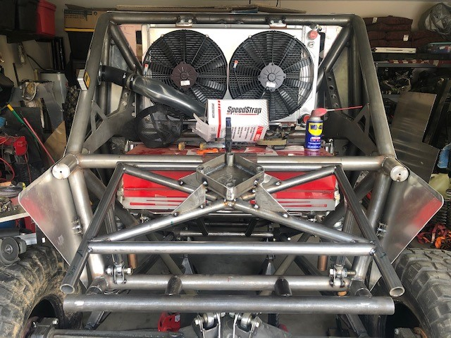
Another reason for the radiator install was to get the final placement of everything so I could get a tire carrier fabricated. To keep on keeping on, I plotted a few ideas in how I wanted to carry a spare. To make things easier to visually see, I threw a spare tire on the back and strapped it down. I quickly realized with a spare permanently in the way, I was losing a lot of space that I could utilize. I decided to make a fold down design that will keep the tire up out of the way, but able to access stuff in the back once folded down. With some spare 1 1/4" tubing lying around, a couple of 3/4" heims, and scrap metal sheet, I created the initial design.
Tire Carrier Design.jpg


After playing with the angles a bit, I finally was happy with the initial mockup and started to add some additional strength to the design.
Tire Carrier Gussets.jpg


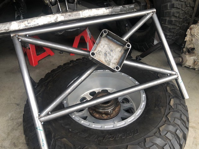
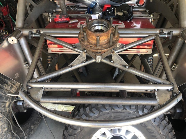
Now the hardest part about this whole thing was figuring out a way to install the tire in the "center". I decided to utilize a "spare" unit bearing on the carrier to hold the spare tire down and keep it centered. This will allow us to have a spare onboard for the long races such as KOH as well. Therefore I used some spacers and flat bar to put together a bearing cup. Although not completely perfect, it'll work well as a spare holder. To get it where it needed to be, I removed the carrier, put an old unit bearing in our wheel/tire combo, installed the cup and tacked the cup in its place. I took a few additional scrap pieces and made gussets to secure it to the carrier.
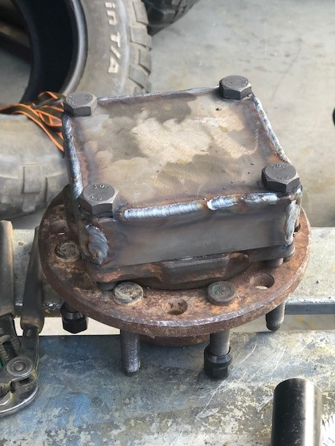
Unit Bearing Box.jpg


Unit Bearing Install.jpg


Unit Bearing Gussets.jpg


To hold the carrier in the "up" position, I used 1/2" t-handle pins on both sides to keep it from moving. Not super happy with how the initial t-handles came out, I later cut them off and used leftover tubing instead of the flat bar. It made the overall design more appealing and stronger. To complete the look of the carrier, I wanted to incorporate a radiused bar on the rear to help with tire support. Unfortunately I do not have a tubing roller so I did what I do best and improvised. I cut the bar I was going to use 6" longer on both sides so I could use my press and press down in 1" increments to my desired radius. To keep it straight, I added a c-clamp to the end of the bar and a degree finder to make sure I pressed in the same degree every time. Pressing 4-5 times in each 1" placement, the bar turned out pretty close. I did have to go back and press in a few places to made both sides equal, but the end result was exactly what I wanted. I then cut off the excess off both sides and added a couple 1/8" gussets to keep this secure as well.
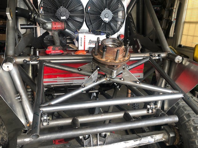
Spare Unit Bearing.jpg


Tire Carrier Overview.jpg


The last thing I needed to incorporate was something to keep it from rotating around. Although snug with lug nuts installed, I wanted to make sure it was as secure as possible. Brainstorming with my wife, she mentioned straps and later got me a Y-strap from Speedstrap to incorporate with the carrier which would complete this portion of the build. I used some 1/4" plate and cut out some tie downs for the Speedstrap. After adjusting the strap and installing the tie downs, the Y-strap completed the spare tire carrier build. Not only did it take care of the rotating, it presses the tire down onto the rear chassis crossbar, and it also adds additional space for PRP's tire storage.
Tire Carrier Speed Strap.jpg


The end result was perfect. It allows us to carry a spare unit bearing which results in studs/bolts and lug nuts, a spare tire, spare 3/4" LH and RH heims (our steering), folds down for easy tire removal, able to access storage underneath, and adds the additional PRP wheel storage with the Y-strap.
 
As we hit 100 days before the attempt of our first race, there's still so much to get accomplished. Although a lot of the big fabrication items are complete, I'm still trying to get the smaller ones taken care of so we can finish welding up the chassis. In order to do that I tackle the front "bumper" next. Luckily this project was quicker and easier to fabricate. I wanted something removable, easily fixable, and incorporate additional spare heims. I used tube clamps for the base design and built from there.
Front Bar Design.jpg


Front Bar Overall.jpg


After taking a few measurements, I got the initial design all mocked up. I then moved to how we'd attach to the top to the chassis. I wanted a design that would allow me to keep the front grill attached. So we went through the gill without cutting anything. I liked the clean look of the grill. Added a few smaller tubes and gussets, then narrowed the front bar and capped it, last thing was to add the small heims (sway bar spares) and mounts.
Front Bar Capped.jpg


Front Bar Gussets.jpg


Front Bar Installed.jpg


In the end, its something that will provide some protection, easily removable/rebuildable, and utilizes additional small spare parts.

While working on this bumper, I was able to land a pretty complete LS1 for a killer deal. We'll just change directions and run this until we can throw some real power at it in the future.
LS1.jpg
 
With the new LS1 and received drivetrain/driveline parts, I figured it was time to go back and rework the front axle so we can start getting the new LS1 installed in its final resting place without any clearance issues. Originally the ram mount I fabricated was too tall on top of the axle, not allowing full bump before the ram clevis bolts would hit the chassis. To eliminate this issue, I lowered the front bar down 1.5" which would allow more than enough clearance. With a lot of back and forth under the chassis and back on the stands, I got it all where it needed to be and started internally gusseting and plating the front truss/ram mount. I welded each section separately tying it all together to build strength and rigidity to the overall design.
Front Axle Internal Gussets.jpg


Front Axle Welded.jpg


After that, I had to work on the ram mounts on top. Unlike most who use only 3 clamps, I went the extra mile to make sure I had the forth clamp on there for symmetry. By using a stud bolt welded to the 9" housing, I was able to incorporate the last clamp. I also finished plating and capping off everything on the top truss.
Front Axle Ram Install.jpg


To finalize everything on the front axle, I had to mock up a double shear knuckle design. Utilizing the designs from Spidertrax, I was able to come up with something similar for these S&S knuckles. With a little bending on the press and careful cardboard designing, I was able to figure out a way to add strength and functionality to the overall double shear design. Although not fully welded yet, I want to make sure no changes are needed before we burn it all in.
Front Axle Double Shear Brackets.jpg


With the front axle all but complete, I stripped the chassis down to finalize the drivetrain which included removing the old 5.3 iron block we used for mock up purposes.
Drivetrain Removal.jpg


The last thing had to do before putting everything back in the chassis was adjust the front upper control arm mounts. They were originally too high and rotated out too much which caused clearance issues at full bump. I simply moved them down 1" and rotated them in towards the front axle which allowed enough clearance to obtain full bump. Problem solved and time for the new components.
 
No Drivetrain.jpg


With the empty chassis it was time to get the LS1 installed. When I dropped it in, I went ahead and bolted up the TH400 as well as our empty Behemoth D300 to finalize the output shaft and motor mounts. With a lot of back and forth with height adjustments and keeping everything centered, I bolted on our headers so we could fabricate our finalized motor mounts. After getting the motor mounts completed, I went to the back and finalized the D300 mount as well.
Drivetrain Mockup.jpg


Motor Mounts.jpg


D300 Mount.jpg


Now with the drivetrain secured, I went back and worked on our oil pan skid plate. I utilized tube clamps from the motor mounts as well as the chassis so it could be removable. I'll probably change the clamp style as I only had locking clamps instead of flat clamps, but regardless I made it work. Added a little bend to the front to help get over rocks and add a little flare. Finished it off with 3/16" plate and counter sunk holes for a smooth bottom.
Oil Pan Skid.jpg


Oil Pan Skid 2.jpg


Oil Pan Complete.jpg


To finish the last little bit of fab work to the drivetrain/driveline, I transitioned to the carrier bearing. Without the front 3rd member, I just temperately put it in its place where I thought it would work. No binding and no clearance issues with the motor mounts/skid, however we'll see once I can bolt in the front driveshaft.
Carrier Bearing.jpg


While I wait on parts, I decided to get the first battery installed... least for now. Enough room to run both batteries side by side here, although still not 100% sure I want these placed behind the seats in this orientation. But for now, it'll work.
Battery 1 Install.jpg


QuotesReply
 
Awesome! I really need to swing by and check this out in person!
 
Its been a while since I've updated on the thread, however I assure you I've still been steady on the build. From the video above, we were able to get a Novak adapter to help with the mounting solution of the transmission to the chassis. That helped complete the powertrain mounting which allowed me to move on to something else. While working on all the mounts, I received our Locked Off-Road bump stops. I started mocking those up in the rear and fabricated some custom mounts for the cans. I integrated them onto multiple chassis bars for extra support. Shouldn't have any issues with them twisting by doing this. Went with a 4" stroke in the rear and a 2" in the front.
Bump Build.jpg


Bump Plating.jpg


Bump Plating 2.jpg


After I got the initial assembly tacked into place, I reinstalled the bump to create a pad onto the axle. When I weld the axle, I'll add gussets underneath. Just made these for now.
Bump Mockup.jpg


Bump Pad.jpg


After getting the driver side done, I duplicated this on the passenger side. Flexed the rear axle and everything looks good. The next day, our Method wheels arrived. Took the next couple of days to get these all painted, assembled, and installed onto the axles.
MR101 Painting.jpg


MR101 x7.jpg


MR101 Profile Rear.jpg


Aside from final coilover installation, the last thing to install on the rear suspension is our limiting straps. To make things easy I simply used double shear limiting strap mounts (non adjustable) and trimmed the axle mount to contour the axle tube radius.
Rear Bump & Limit.jpg
 
I'm getting a little burned out on the everyday fabrication of the same old stuff. Instead of installing the bumps and limit straps on the front, I decided to go back and finish up some of the stuff I had left unfinished before and finish it up. This included the rear interior panels, harnesses, mounts, and the rear flooring. The rear upper panel was easy, I needed to cut out where the harness mounts would go and install a wire mesh for protection. But the lower panel wasn't as easy as I had to cut out a portion for the batteries since they stuck out 1". In order to make them quickly accessible, I used some leftover aluminum and made a "cover" so to speak with a few bolts holding it down. Since I don't have a TIG for aluminum, I had to bend everything and rivet it together.
Rear Panel Screen.jpg


Back Panel Battery.jpg


Battery Cover.jpg


Battery Cover Complete.jpg


Glad I was able to come up with a decent solution the the aluminum paneling because the next thing was to do the same thing to the rear flooring. This was TIME consuming getting everything bent in the correct location and notched. The end result was dang near perfect though.
Flooring Rear.jpg


Flooring Rear corner.jpg


Flooring with mounts.jpg


After I got it all installed and completed, I threw the seat in there with the harnesses to complete the interior... least for now.
Harness install.jpg


Aside from some small fabrication things, I was able to get something fun installed. Ever since I was little, I always loved the KC lights. I wanted to make sure I incorporated some on Tinkerita so I bought some for our headlights. Although not important right now, definitely made a difference in the appearance. Sometimes its the small things that keep the motivation alive.
KC Headlights.jpg


As of right now, we're doing small things in preperation for everything on order. Within the next few weeks, we'll have our 2.5" coilovers, front and rear sway bars, brakes, lights, 3rd members and a few other goodies. Stay tuned... I'll do my best to keep it updated.
 
Back
Top