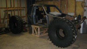
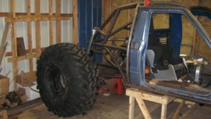
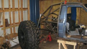
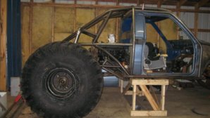
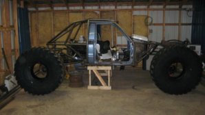
rear engine rear steer truggy

I had to get a cup to catch the drool while I looked at the pics! Now I really want to get down there for a visit. Good job Bro!
 
The tube "lines" look awsome. Please educate me, front loaders? what yrs. guessing military. Where to get more info on them? And for the grand finally- rear engine? correct rotation and all that? Thanks, I don't frequent other boards so I was hoping you could share some insight. By the way your work pace makes my projects look like they are disassembling themselves.:beer:
 
The tube "lines" look awsome. Please educate me, front loaders? what yrs. guessing military. Where to get more info on them? And for the grand finally- rear engine? correct rotation and all that? Thanks, I don't frequent other boards so I was hoping you could share some insight. By the way your work pace makes my projects look like they are disassembling themselves.:beer:

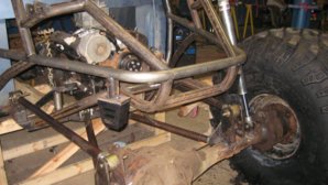
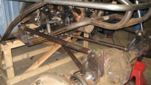
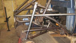
axles are 1950's gmc 2.5 tons. they used them in the duece halfs before the rockwells. they are front load with a removable third member, high pinion. they spin the wrong way hence the rear engine. they are geared 6.17. the only down side it they are ball and claw and hard to get parts for, but the price was right so what the heck.
 
I'm not trying to highjack by asking questions, just trying to learn a bit, thanks for the info. When you say they spin wrong is that due to a non-reverse rotation gear placed in a high pinion configuration or some more millitary modular planning where you can some how flip the center chunk or something. Either way seems its benificial since your drive line doesn't have to exit so high like a traditional Rockwell.
 
its a normal ring a pinion set up just spinns backwards. i gues the military t cases just spunn the wrong way
 
progress

well made a little progress, rear four link is pritty well set up. this thing should be rolling pritty soon.
 

Attachments

  • truggy7 001.jpg
    truggy7 001.jpg
    41.7 KB · Views: 936
  • truggy7 013.jpg
    truggy7 013.jpg
    54.9 KB · Views: 912
  • truggy7 019.jpg
    truggy7 019.jpg
    56.6 KB · Views: 885
more pics

pics
 

Attachments

  • truggy7 015.jpg
    truggy7 015.jpg
    65.7 KB · Views: 899
  • truggy7 005.jpg
    truggy7 005.jpg
    61.9 KB · Views: 845
  • truggy7 003.jpg
    truggy7 003.jpg
    61.2 KB · Views: 878
pics

pics
 

Attachments

  • truggy7 008.jpg
    truggy7 008.jpg
    32 KB · Views: 840
  • truggy7 012.jpg
    truggy7 012.jpg
    48.6 KB · Views: 839
  • truggy7 014.jpg
    truggy7 014.jpg
    52.3 KB · Views: 868
Man that thing looks fawkin awsome. Those are some BIG a$$ tires. What is your wheelbase?
 
Tim, can you explain these axles a little more

I understand they are reverse rotation, so you put your engine in the rear, can you not flip the third and run a front mounted motor

and also how are they brakes set up, I am guessing it being a front loader your running wheels brakes instead of pinion brakes like rocks

reason for the questions, I am going to look at a set on Sat
 
Tim, can you explain these axles a little more
I understand they are reverse cut, so you put your engine in the rear, can you not flip the third and run a front mounted motor
and also how are they brakes set up, I am guessing it being a front loader your running wheels brakes instead of pinion brakes like rocks
reason for the questions, I am going to look at a set on Sat

i am going to still run some kind of pinion brake setup. you can flip the third member over, then you have to fip the axles shalfs also. the only thing with that is the shalfs are not the same length. so you have to cut one of and spinn it about 3/4inch, and the other will have about an inch of play. also it won't be high pinion. if you decide against these axles let me know, i might need some spare parts.
 
Back
Top