

You are using an out of date browser. It may not display this or other websites correctly.
You should upgrade or use an alternative browser.
You should upgrade or use an alternative browser.
Jeep SBEC PCM tuning (91-95)
- Thread starter a_kelley
- Start date
AdamRosas
Member
- Joined
- Sep 3, 2021
- Location
- Portland OR
I got it working, still needs a bit of work but the Jeep drives fine, RPM calculation is off so it idles rough
and has a flat spot when accelerating. The clock for the other two undocumented chips is derived from
the MCU clock so they are overclocked as well, not a lot of divide by 3 options are available in the MCU
so the SPI bus is overclocked from 500kbs to 750kbs but seems to be working fine. I got some 16Mhz
crystals comming in the mail, if the MCU will tolarate a 4Mhz ECLOCK it will make things much easier.
Last edited:
There was a dude on jeepforum, went by Que89YJ, that if I remember correctly helped engineer these things originally and may be a great resource on this project. Doesn't look like he's been active on there in a couple years though.
AdamRosas
Member
- Joined
- Sep 3, 2021
- Location
- Portland OR
The SPI bus breaks at 16 mhz, everything seems to be operating correctly, until I try to start the engine. I messed with the
prescaler for the SPI bus but no luck, I was able to use the ECLOCK pin to clock the undocumented chips to their stock clocks

prescaler for the SPI bus but no luck, I was able to use the ECLOCK pin to clock the undocumented chips to their stock clocks
AdamRosas
Member
- Joined
- Sep 3, 2021
- Location
- Portland OR
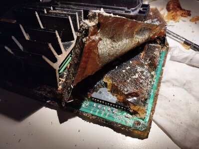
I finely had time to dig into the V8 Jeep ZJ ECU with P/N 56029302, I discovered
that it had an oldtimey UV erasable EPROM and the parts to supply the programming
voltage wasn't installed. Here are a few pics of what has to be changed to make this
ECU flashable.

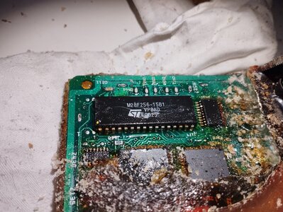
Add a flashable EEPROM

under the EPROM move the jumpers as shown and add the 20k resistor (green 203 part).

add the 8L12A voltage regulator, sill available from mouser and the like, this regulator
supplies the 12 volts needed for programming, add the 100nf capacitor 50 volts, I think.
add a transistor, not sure of the specs of the transistor it has R2X marked on it and I pulled
it from a parts ECU, a factory flashable unit has a transistor with marked 87S or B7S in
that spot.
And that's it the ECU can now be flashed via the diagnostic port.
that it had an oldtimey UV erasable EPROM and the parts to supply the programming
voltage wasn't installed. Here are a few pics of what has to be changed to make this
ECU flashable.
Add a flashable EEPROM
under the EPROM move the jumpers as shown and add the 20k resistor (green 203 part).
add the 8L12A voltage regulator, sill available from mouser and the like, this regulator
supplies the 12 volts needed for programming, add the 100nf capacitor 50 volts, I think.
add a transistor, not sure of the specs of the transistor it has R2X marked on it and I pulled
it from a parts ECU, a factory flashable unit has a transistor with marked 87S or B7S in
that spot.
And that's it the ECU can now be flashed via the diagnostic port.
AdamRosas
Member
- Joined
- Sep 3, 2021
- Location
- Portland OR
I soldered some tiny wires to the transistor from the factory flashable ECU and discovered I installed a NPN
transistor, but needed a PNP in that location

So I installed a PNP transistor marked with R2T, but that broke flashing, so on to finding more missing
components.

on the top side of the board I had to add a diode, any old diode that can handle 20-ish volts

and another 100nf cap

on the bottom of the board I had to add 2 - 1k resistors.
Now the circuit operates the way Chrysler engineers intended.
transistor, but needed a PNP in that location
So I installed a PNP transistor marked with R2T, but that broke flashing, so on to finding more missing
components.
on the top side of the board I had to add a diode, any old diode that can handle 20-ish volts
and another 100nf cap
on the bottom of the board I had to add 2 - 1k resistors.
Now the circuit operates the way Chrysler engineers intended.

sh0velhead
New Member
- Joined
- Oct 19, 2022
- Location
- Sweden
Thanks Adam! Wonder if I can use your bootsrap code with the stuff Andrew and I wrote to be able to flash toshiba chips. My main ECU has the toshiba chip. My spare one that had the ST chip that I could write to needs to be re-potted.
Anyway, I recently spoke to Akelley. Poor guy has gone through some major life changes and this project is on hold for him. He offered to give me whatever code he had left for this project and said he's happy to allow me to post it on Github.
I've got some renewed interest to get tuning and flashing for these jeeps off the ground, but im no engineer, I know a tiny bit about assembly language, and have a very fundamental understanding of EFI concepts. But I do have sheer persistence.
If we got enough will, and people with the right skills, I'd love to continue this project. Raise your hand if you can help!
I would love to see his work on github. Not sure if I can help in developing any software, been many years since I programmed anything but I might be able to help with a hardware interface.
Best regards,
Robin
autopar3000
New Member
- Joined
- Oct 27, 2022
- Location
- Toronto
sev80
Active Member
- Joined
- Jan 21, 2017
- Location
- Los Angeles
@AdamRosas nice work! Curious why you needed to overclock the v8 ecu's? Are they clocked slower than the i4/i6?The SPI bus breaks at 16 mhz, everything seems to be operating correctly, until I try to start the engine. I messed with the
prescaler for the SPI bus but no luck, I was able to use the ECLOCK pin to clock the undocumented chips to their stock clocks
View attachment 380993
For some reason I wasnt getting notifications that this thread had activity. Good work!
I wish I had source code to put on Github,... a while back Akelley reached out and said he was going to give me all the remaining code/work he'd done on building tuning but I never heard back.
Also Adam, another guy on Jeep Forum also backed up the DRB super cart. He actually designed a PCB to build clone v8 super carts as well.
BTW - I spent a few months doing a deep dive on the russian jeep forums. It was pain staking using google translate to read 120 pages of forum posts, but those guys were doing similar work and one guy actually built an app using the DRB code to do data logging and diagnostics. Fortunately, the author of the app translated the final versions to english.
The one cool thing with that app, I discovered was that while the DRB allows you to retard timing as a global variable, there's apparently nothing in the ECU that stops the timing being scaled to advance. So their tool can adjust the timing variable to allow for timing advance. I tried it briefly and it worked but I ran out of time and havent gone back to mess with it more.
Using the same cable akelley and I built for flashing, you can use this program for diagnostics and logging on all the sensors to a graph.
Attached here: It's called CDT. I tried using google translate to email the author for the latest version, and he never responded. But I did manage to find a copy of the second to last revision. The russian jeep forum uses a very old version of Vbulletin and trying to register there for an account to download this was impossible, but I managed to dig around and find it on another site that's really cool.
Basically other russian site, the guy explains how all the calculations work in the ECU and provides a basic schematic. Could be useful to continue tuning efforts.
I wish i could code assembly
")
anyway, the CDT program is really cool! This app negates the need for a Drb II pretty much.
Attachments
Last edited:
sev80
Active Member
- Joined
- Jan 21, 2017
- Location
- Los Angeles
it would be SO awesome to get a hold of him and hear his stories and get his help. wow.There was a dude on jeepforum, went by Que89YJ, that if I remember correctly helped engineer these things originally and may be a great resource on this project. Doesn't look like he's been active on there in a couple years though.
I just PM'd him and linked him to this thread. hopefully he joins
Last edited:
sev80
Active Member
- Joined
- Jan 21, 2017
- Location
- Los Angeles
it wasn't with MPtune, Andrew wrote a program to dump/flash the later flashable SBECs. It was pretty much in alpha state and only worked with PCB's that had ST Micro eeproms. Though I think Adam Rosas figured out how to write to the Toshiba ones.Hi,
I got a read from my 1995 grand cherokee ecu using the usb cable in bootmode with mptune, but was wondering how Sev80 got to write to that its the flashable version with small pcb.
sev80
Active Member
- Joined
- Jan 21, 2017
- Location
- Los Angeles
look up RDCZJ on Jeep forum. He is taking a full schematic of these SBECs and should be able to tell you what that transistor is. I linked him to this thread, hopefully he can help you out.Hi, i have one missing part, maybe transistor, can anyone tell me what type(spec's) it should be?, thanks
View attachment 404241View attachment 404242
That package can be quite a few different things, but that one is a Diode, technically 2 Diodes in there, so a Diode array, Common Anode. SJ F is the original part number on the board I tore down here, yours look like SJ C. Last letter is probably some date code or something, and no idea what it would exactly cross to, but I'd toss a BAS70 or similar in there.
This was all done off of the 4.0 ECM, 56028 026 07/20/94. Anything 5.2 related in the schematic is just speculation and circled, until I have one to tear apart and confirm or change it.
The PCB has no component designators from the factory, the white writing on there like C1, R8 etc., etc., that you see on most circuit boards, so you half know what is what. I had to mark all of those, and without these images the schematic is only kind of useful. The 5.2 components are also not listed on the designator images until I can find out what is really what there. Any not populated locations are also not marked, as it would be a crap shoot to guess what might go there.
All of the thru hole and any large components have been removed to get a better scan of the PCB. The board is 4 layers for anyone interested. The 2 internal layers are just ground and the different power rails.
Links to better images, the forums 1k limit is wrecking the quality as the originals are almost 10 times that size.
TOP - https://www.acidmods.com/RDC/Jeep/ECM 94/Top Designators.jpg
BOTTOM - https://www.acidmods.com/RDC/Jeep/ECM 94/Bottom Designators.jpg
Attachments
Last edited:
Damn, that's amazing stuff there.This was all done off of the 4.0 ECM, 56028 026 07/20/94. Anything 5.2 related in the schematic is just speculation and circled, until I have one to tear apart and confirm or change it.
The PCB has no component designators from the factory, the white writing on there like C1, R8 etc., etc., that you see on most circuit boards, so you half know what is what. I had to mark all of those, and without these images the schematic is only kind of useful. The 5.2 components are also not listed on the designator images until I can find out what is really what there. Any not populated locations are also not marked, as it would be a crap shoot to guess what might go there.
All of the thru hole and any large components have been removed to get a better scan of the PCB. The board is 4 layers for anyone interested. The 2 internal layers are just ground and the different power rails.
Links to better images, the forums 1k limit is wrecking the quality as the originals are almost 10 times that size.
TOP - https://www.acidmods.com/RDC/Jeep/ECM 94/Top Designators.jpg
BOTTOM - https://www.acidmods.com/RDC/Jeep/ECM 94/Bottom Designators.jpg
Thanks. It's not perfect, probably never will be, but given the original will likely never see the light of day this might be useful to someone at some point. It's about as accurate as I can get it without spending loads more time on it and poking around inside of a working one. I actually rebuild the PCB from the schematic, in the same software that I use to make the schematic, to make sure the traces match the original board and that things are connected correctly.


If anyone notices anything wrong or has any info on anything in there, like U9 in the power supply, let me know. I spent too much time as it is looking thru as many old Motorola datasheets for SMPS chips that I could find and nothing came close.
If anyone notices anything wrong or has any info on anything in there, like U9 in the power supply, let me know. I spent too much time as it is looking thru as many old Motorola datasheets for SMPS chips that I could find and nothing came close.
So, I got the supercharger built on, modified the stock bin file to run more fueling.
With stock bin it was seeing 1.1 lambda under boost; modified it hovers around 0.82 WOT.
Next step would be to get the 2 bar map sensor in and recallibrate the maps to have some lines for boost.
I've tried this. Setting the multiplier to 02. (8021 address). Car starts up but immediately dies again.
I think there is something preventing boost values over Atmospheric (many subroutines compare map to atmospheric). I would like to find how it gets to open loop too, as now it seems to do it only from 2750 rpm up, lambda stays at 1.05 then jumps down to 0.82.
;Data To Convert MAP
8021 00 D8021 FCB $00 ;Not mul ***** changed to 02
8022 00 D8022 FCB $00 ;Not ADD
432 F68021 AE432 LDAB D8021 ; **** now 02 value
E435 2701 BEQ AE438 *****branch if zero to E438
E437 3D MUL
E438 F38022 AE438 ADDD D8022
E43B 2402 BCC AE43F
E43D 86FF LDAA #$FF
E43F 39 AE43F RTS
I've also noticed that the rpm limiter stock on my 2.5 is higher than for the 4.0.
Last edited:
What's an EM-cover ?Bought some used pcms and this one was a bit weird with an em-cover on top of the chip and processor.
That's interesting.It's an RF shield, to keep any high frequency 'noise' from interfering with it and/or to keep it from interfering with anything else. Not all of that version board have that installed.