Somthing

Anyone know how the output disconnects attach to the output shaft? Thinking if I could include that part into anything I end up doing.

Ok, I guess I was a little confused, the above mentions nothing about a Toyota output.
 
I have a few sets of old Toyota gears, could you maybe use the pinions , turn them down to fit into the side gears of your existing case and weld the carrier and the stubs, yes, it would be a one shot deal, I know, just an idea........

I think I have at least one Toy T'case output was well.....
 
sorry thought you were up on the toyota shit :)

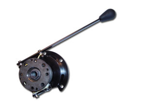
something along this line...
frontrange-disco.jpg
 
Oh yeah, tossed 3 of those away last week, got tired of tripping over them, never could figure out a good use for 'em after getting rid of the Winnebago....
 
I don't see why you couldn't weld a piece of round stock or thick DOM into a thick piece of round plate, put it on a lathe and make a spool? Or do like everyone else and weld it.
 
welding it up is an option, the reason im looking to avoid that is that leaves me having to use modified 1/2 shaft inserts, with a yoke or flange welded onto those.

This would be fine for the front where there will be a 2joint shaft and a carrier bearing would prevent the spud from sliding out.

For the rear shaft id rather not rely on the clip as the only way to retain the shaft/flange to the transmission. A drive shaft slip yoke can get stiff or even with a little tension would still pull out the clip.

So...... if i had something made up it would have provisions to either use a 1 piece splined shaft that would take a standard toyota yoke or even possibly have a spline section protruding out to take the flange...

I just see the time/effort spent up front to atleast evaluate some options, being better than slapping band-aids after the fact on a problem I can easily see having..

Also supported flange design would allow me to easily attach any of the standard aftermarket disconnects.
 
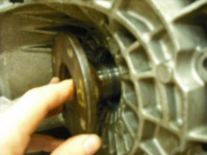
I removed the seals and the ring gear to make it easier to handle the carrier.

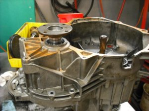
The is what I have in mind. And after some measuring I think the best way would be to make a 'spool' with Toyota pitch internal 27 spine all the way through. Then a shaft with external 27 splines and a threaded end to take a standard lock nut on the end.

The diff/chunk is 6.5" Diameter and only 5.5" thick.. so not a big piece of stuff to start with.

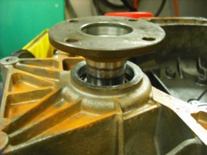
I found a seal that will work with the 27spline flanges. Flanges fit nicely on the inside end and the other side clears np.

Still need to investigate the disconnect.. to see how they attach..

20090618-F23 010.jpg

20090618-F23 011.jpg

20090618-F23 018.jpg
 
I'm betting you'll pay twice as much for that splined shaft as you paid for the whole transmission. ;)
 
I don't know if you've priced those disco's before...but it would be far cooler if you threw all of that money at rear steer instead.
 
Yes the discos are not in my budget at this time :) ($499) But that's why I'm posting up... I figure if I sound dumb and ask stupid questions you all will jump in and show me how smart you are... But if I sound like I know what I'm doing everyone wan't to see ya fail.. I'm glad I'm the topic of conversation. I still have the camper :)

Seats? Greg....... Greg...... Greg........ Have I got a deal for you....

I'm asking about stuff because I know alot of people have their hands into a lot of things or have some wild idea that might just work... So if anyone has any ideas on a lower cost disconnect vs shelling out for the bling, I'm listening.

I'm trying to stay away from rear steer. Weight and cost is a big reason.. but maybe down the road who knows..
 
Yes the discos are not in my budget at this time :) ($499)
Whoa...thought they were cheaper than that...

Spend that money on a rear e-locker then...with a little cutting brake action and a blip of the throttle you can spin a 180 faster than any rear steered anything...with the front and rear both 'connected'...
 
ya tell me about it.......I was wanting to run a T100 rear axle (long story/short) and there isn't an elocker for them. Probably what will happen is it will get put together as best as i can do to meet my budget goals and then I will look for some stuff to add down the road..

I agree with a good brake setup and a smaller rig a tight spin is pretty easy. I love watching guys with rear steer work, but I just dont think it worth the extra weight or hit on my budget..

[part of my budget is to see how far i can go with it and what I end up with... also keeping in mind I'm willing to spend my time or wait for good deals on used stuff...]
 
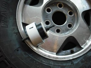
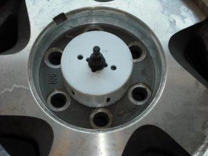
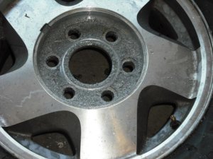
wheels - I didn't feel like paying $$ to have the centers enlarged on my chevy wheels to fit on the toy hubs so I decided to see what I could come up with... :driver:
Basically using a 4-1/8 hole saw with the bit removed and a modified 1/4" bolt as an extension connecting to a 3" hole saw with some tape wrapped to fill it out some to make a snug fit in the hole... Coming out nicely...
20090620-VanAC 012.jpg

20090620-VanAC 011.jpg

20090620-VanAC 013.jpg
 
My $10 drill wasn't to happy with my pace.. I need to break out the Bosch drill and be done. I almost hate using that thing as I always end up hurting my self somehow. Anyway. I'm almost done with the first one and not counting the cool down periods ~10min at a slow pace.. The alum is cutting pretty easy...
 
Cool. I have a heavy duty Milwaukee 90 degree drill you can use if you like. It's easier on the arms and wrists when drilling with big hole saws.
 
you were talking bout doing disc brake conversion on a toyota axle was to expensive i done mine for less than $40.00 i used rotors and calipers off of the rear of a nissan pathfinder i think it was 95'ish from pull a parts in charlotte. i made the bracket out of 3/16 steel and added another small piece of 3/16 steel where the caliper mounts to space the caliper close enough to the rotor and it works great. if you get the brake hoses too they will screw rite in. the only thing i had to do to the rotor was turn the center hole out, but you look like you got that figured out. hope this helps. happy fabing
 
20090712 - Update

updates
wheels - Thanks for the drill press tip guys, I tryed to fit the wheel and tire up on there it just wouldn't fit :flipoff2:

disk conversion - Thanks for the pathfinder tip. They do look like they will work out, I'll have to make a trip to the J/Y and grab some stuff.. If that PnP yard was closer I'd grab the whole axle !!!!

I've figured out a few things and collected up a few more parts hopefully pointing me in a better direction overall.

transaxle - I got the transaxle and got it taken apart enough to figure out I wanted a spool or sorts in there and a shaft to allow me to bolt on 2 toyota flanges for the drive shafts to attach to. Chase at ECGS had a good idea to just spline the inside of the carrier, the stock carrier was sorta oversized for the small 1/2 shafts that were fitted in there. Then with a small ~10" long splined shaft inserted all the way through I will be able to attach the toy flanges. I spec'd out a seal that will fit the transaxle case and the same ID as the toy flange. So thats sorta in the works... Chase will be working with Brankic to get the carrier and shaft work done for me.

Axles - With the transaxle sorted out, I decided it would be better for several reasons to look for 2 E-locker diffs to run. This will be my method of dealing with the transaxle having no method of unlocking the front or rear. I figured locked in with open/open is probably the preferred way to wheel the easy stuff anyway. Then I can engage the diffs as needed. Additionally the elockers are V6 sized chunks for what ever benefit that may provide me. I'll also be running 5.29s as one of the elockers had that to start with so that helped make my decision on gearing.
-- Because I'll be running the chunks flipped (rear engine), this puts the elocker engagement motor down low AND because one of my elockers is missing the motor, I'm looking for an alternate way to engage the lockers. I have a few ideas but am considering all options at this point.

Seats - I order some seats from the PBB vendor selling them cheep. As luck would have it, I'm planning on a light/machine gray colored buggy. I was worried about the quality but as Gavan pointed out, even if they aren't great and I don't like them, they will be sufficient to build around and at worst I sell them for a small loss and upgrade in the future. But reviews seem to be positive. Plus my seat 'loading' isn't as much as some people, so I'm sure they will be fine for me. The seats actually come in Friday and I think they are pretty nice for the $ and in fact will work just fine for this low cost project.. Definitely glad I decided to go with them.

Engine - Not sure if i updated this or not, my motor has a bad head gasket, zero compression on 2-3, np. thats one of the big fail points on these motors anyway. Options are to do a stud kit/head gasket to repair it for ~$200 or grab another motor ~$200... I'm still money ahead with parting out the car as I have many parts i otherwise may not have recieve just getting a motor. radiator/hoses/harness/PCM/battery/tank/lines/etc..

Wheels - using 4-1/8" hole saw to enlarge my chevy wheels, need to enlarge ~1/16" more using. I initially was planning to use a flap disk wheel but its OD was close to 6" and it wouldn't compress enough to work. So I ended up just buying a cheep roll of emery cloth and taping it onto the hole saw. After a few tries I found that if I inserted it into the slots on the saw and taped it on the inside it worked great. At a nice slow speed, it took ~5min maybe to clean it up nice and the natural wobbling of the hole saw and myself worked to even out the sanding :) I plan to work on the others this weekend. As I need to mount the tires to help with the layout stuff...

Shocks - I've started reading up on air shocks and stuff. Looks like i'll be doing some tuning and re-valving on them to make them work the way I will want. Based on research I can clearly see why some like them and other do not. Most seem the think that you simply adjust the oil level and charge them. Yes that's mostly correct, your adjusting the rate/height aspect, but your not tuning the 'shock' part. So unless you supplied your weights and desired compression/rebound shock settings for them to be set that way, you received a default setting that may or may not be correct for your rig or your liking. Also there seems to be some use of bump stop pistons in the shock. The added bypass holes help with the leaning/side hilling that many fix with a sway bar. And additionally with the correct amount of oil they can also be used as the bump stop on lighter rigs. Still lots of homework but this gives me something else to spend some time on if I'm sick of the other stuff.. I still have my vendor PMs with great pricing but I simply have been buying other higher priority items first, and spreading the spending out a little.

What's Next -
- When seats arrive I should be able to start doing some preliminary layout work.
- Fab up a small 3rd member holder to better work on the chunks.
- Drag my frame dolly up to the garage and make some modifications so I can better move it around the yard (in/out of garage) to save time moving it so I can work on other stuff as needed.
--- I need to add some feet to the bottom so I can level it (and lock it in place)
--- I need to attach the engine/transaxle to the dolly so i can build the mockup chassis around it at first.
- Mock up - Yaaaay! I have some 3/4" plastic conduit I plan to use to rough in and visualize the overall layout.
--- I hope to start on this part as soon as I complete some predecessor steps.
--- I expect to be in this phase for a while. Getting to this point has been what i've been pushing for, for several reasons.
-- I can leave stuff in place on the dolly and move it around.
-- Begin initial suspension planning/layout/design I will be seeking inputs on this as I proceed.
-- I have several chassis designs in my head and I'd like to meld several of them together.
 
Ill have to keep that in mind when I get to needing a running motor.
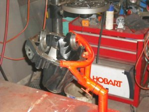
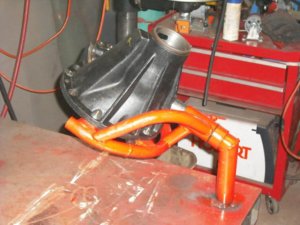
Anyway. I made this on Sunday... I made a simple version a few years back but always ended up moving it around to get to the pinion side or a different position etc..
Its just some 1-3/4 tube with some 1-1/2 tube sanded down for a loose slip fit..
I got the angle so it more less spins it in the plane I wanted to be able to work on both sides, and its balanced pretty well also. Its tacked to my bench now for testing :) but I will make a base plate I can clamp to the bench when I need to use it.

20090714-Parts 008.jpg

20090714-Parts 009.jpg


yesterday I drilled out 2 more wheels, I might finish them up today... maybe not...
 
Back
Top