84 CJ Truck Build (Project Do-Over)

Well... after taking a minute to measure out (and eyeball) my carb flange, there's not enough meat there to redrill the bolt pattern to flip it 90*. So I'll either have to make an adapter to turn the carb, or make an adapter for a throttle body. Either way, looks like I'm making an adapter.

In other news, some research shows that there is a mod kit and associated firmware upgrade for the lesser expensive ECM option. Pretty simple...swap out one transistor for another, add a diode and a jumper and you're in business to run a PWM IAC. It would really be all too convenient for a mod to be available for the less expensive ECM to run a stepper motor IAC, since that's what's on most of the throttle bodies that I'm finding... but that's cool. At least I won't have to cough up an extra Bennie for the ECM just to be able to run the stepper IAC. Either way I go (throttle body or modded carb) I'll just run a PWM IAC. This will be much better off than me just running the on/off type fast idle valve. I think I'd be pissed if I got all the way through this EFI project just to have it stall occasionally because I don't have some sort of idle control... :rolleyes:
 
IMG_1859.JPG


Not trying to reinvent the wheel here... just trying to keep things simple.

More progress has been made. I've decided to make my carburetor a throttle body. So I punched out the boosters so the venturis are straight through. All the ancillary components have been removed. I made some block-off plates for the metering block mating surface. I don't have a picture of them because they are a rather simple aluminum plate, machined to size and 4 holes drilled. Oh, and squirted some paint on them so they don't oxidize. As soon as I source some short, rather obscurely-sized #12-24 bolts, I'll stick them to the throttle body and have some show and tell. In the meantime...

IMG_1852.JPG


Here is my "new" throttle body. It'll flow an asswad of air since the boosters are gone now. If I had to guess, I'd say that it's similarly sized to the 1000 cfm 4150 throttle bodies out there. I knocked off the trans kickdown tab and rounded it off, and found some paint in the cabinet that was a damn close match to the color of the linkage. Almost looks like it came that way now.

IMG_1857.JPG

There's enough room in there for everything to move without interfering. I'll just put some 90* elbows at the inside ends of the rail sections and use a u-shaped piece of tube to connect the rails.
IMG_1856.JPG


The far vacuum port is very close to the rail, but I should be able to get a hose connected to it. If not, I'll either try to bend it slightly or shorten and flare it.

IMG_1858.JPG


Visual aid shown here that the throttle linkage goes full stroke without hitting anything.

Oh yeah, also put some color on the manifold so it looks like one piece again. I wasn't sure if I would like a black manifold, but I guess it'll work. That doesn't sound racist, does it? :lol:

I'm also making headway with some rail hold downs. I've got most of one made (woohoo...), but at least I know what I'm doing with it now. I've just got to cut and bend some more sheet metal as time allows, then stick a few pieces together.
 
It's time to put my nerd hat on for a minute...

error-system-shutdown-error-nerd-geek-system-shutdown-funny-demotivational-poster-1253798798.jpg


Since I am quite the geek at heart, I think this is pretty damn cool. I downloaded an IDE and was able to compile the required code to load onto a microprocessor to create a tune for running my engine. Here's a screenshot of some of the code:

Speeduino.jpg


I didn't write the code obviously. While I do have programming experience, this would have been waaaay too damn time consuming for me to pull off. As you can tell by the screenshot, this is from the guys down at Speeduino. A guy by the name of Josh Stewart created this open source code as kind of a tinker toy, but then decided he was awesome enough to put it up on the interwebs for other tinkerers to enjoy.

The awesome thing about this being open source code is that if I were so inclined, I could write the code to make additional and/or modify functions for the engine tune...or other things on the CJ. Maybe I will, if I come up with something truly worthwhile.

I'll load this onto an Arduino-compatible Mega 2560 microprocessor, then build a shield for it to be the go-between for the microprocessor and the engine (sensors and injectors and crap, really). Now that I know my derelict computer is capable of handling the IDE I downloaded (Arduino), and successfully compiled the Speeduino code, I'll now get the microprocessor and load it up and create an engine tune in my TunerStudio.

I'm so geeking out on this, it ain't even funny....

C6kQd24WoAA6qZd.jpg
 
So, rather than it running the FI, it plays middle man to fool the OE ECM that everything is stock/or sensor data is within stock specs??
That could be done, if I were using an OE ECM. In this case, I'm starting from scratch...building a harness, the ECM and everything. This one will be running the EFI. One could use this system to fool an ECM into thinking everything was stock, though.

The Arduino development boards can be used to do nearly anything you can imagine...you can make a GPS, a cell phone, a clock, a robot...remote control...turn it into a modem or WiFi catcher, make a voice box and sound like Stephen Hawking, and obviously run spark and fuel tables for an EFI system. I'll be starting "easy" though and only be running fuel control since I already have an MSD ignition system. Maybe one day if I'm feeling froggy, I'll create the spark tables and get a computer controlled distributor and have it run that, too. Or, I could also retrofit an oil pump drive from a Vortec engine and go distributorless...wouldn't that make some people scratch their nuggets when I raise the hood! ....that's all obviously riding on the fact of if I ever get this thing out of the garage again....lol
 
Or, I could also retrofit an oil pump drive from a Vortec engine and go distributorless...wouldn't that make some people scratch their nuggets when I raise the hood! ....that's all obviously riding on the fact of if I ever get this thing out of the garage again....lol

I have thought about similar thoughts. Basically, LSx EFI has gotten so common and modifiable that you should be able to adapt it to almost any engine, similar to TBI systems.
 
You can even get a timing cover and distributor gear drive for an LS and run a carb.
 
You can even get a timing cover and distributor gear drive for an LS and run a carb.
One of these years, I'm gonna get me one of those! I've got a dream build that keeps haunting me... just don't know when, where, and how much just yet.
 
So what are we looking at here? A gutted carb, and fuel rails? how do they talk so that your fuel is proportionate to the air?
So they DO exist...another Pennsyltuckian on the NC4x4...

Yes, that's exactly what we're looking at. A carburetor is a throttle body. A throttle body is almost a carburetor. The fuel rails don't really do any talking at all...they merely deliver the fuel to the injectors, which are instructed when to fire by the ECM (not yet constructed...still working on gathering a pile of MOSFETs, diodes, resistors, a handful of capacitors...a PCB to solder them all to would help).

What you don't see yet is the TPS that will be added to the primary throttle blade shaft. This will communicate with the ECM, as well as the onboard MAP sensor, and a wideband O2 that will be added as well. The engine will be tuned to run on speed density, and the fueling will be controlled by a volumetric efficiency table that calculates fuel based on engine speed (another signal to the ECM as well), and the MAP sensor. The wideband O2 will make the fine-tune adjustments. I'll also add in a pulse-width modulated idle air control to aid in warm-up RPM. The rest is just gravy.

But have patience...this will take a while, because my time in the garage is incredibly limited at the moment. I'm still gathering spare change from my couch cushions and the sidewalks at any available moment to fund this. :D
 
Little mini-update here...

I was going to wait until a couple things showed up so I had pics fo' proof, but I guess I just got too excited. :rolleyes: I've ordered the microprocessor, and it should be here by next week. Then I'll load the firmware and see if it'll take a base tune without any guts on the PCB. Not sure, but I think it "should..."

In other news, I also ordered the PCB. Oddly, these two items were the cheapest things on the list. I've compiled a BOM of all the little bits and trinkets and junk that need to get stuffed into the PCB for it to actually function. Almost as odd as the previous statement, those little craps are the most expensive part of this EFI conversion (thus far, anyway). I'm just working up the nerve to pull the trigger on $81 plus the ride to get that pile of goodies. After all that gets here, I'll have to crank up the soldering iron and get to work. Hopefully I don't let out the magic smoke.

I'm also considering getting this going initially with a narrowband O2 to get things running, make sure I don't have any wild issues, and to save ~$100 initially. We'll see, maybe I'll just pony up the bread when that time comes.

Okay then. Carry on, but stay tuned.

041810_Demotivational_Posters_1.jpg
 
Last edited:
I forgot how much of a cheap ass you are....
 
I forgot how much of a cheap ass you are....
I'd like to say "it's all part of the challenge," but sometimes my cheap-assed-ness comes back to bite me right square on ... well, the ass. But yeah - you remember the good old days! Maybe one of these years the boss will let me have a real allowance so I can go play :lol:
 
IMG_2023.JPG


Oh, wait... here it is!
IMG_2026.JPG


That's the microprocessor that will soon be loaded with the firmware for running the engine. If I'm feeling froggy (and I always am), I may plug it into the puter and see if I can load anything on it without the PCB populated.

Speaking of the PCB...
IMG_2027.JPG

It showed up in the mail yesterday! Now I've got to get $100 worth of junk to stuff into this bad boy. That little guy there on the right?
IMG_2028.JPG

Not much bigger than a thumb nail... soldering on the MAX9926 is going to be fun, lemme tell you...
 
Sooo.... this is now the coolest damn toy in my arsenal at the moment. :D

Recompiled the firmware, plugged in the microprocessor (had to install a driver for it to connect properly), and it's alive!
IMG_2029.JPG


Decided to play my luck at uploading the firmware... no dice the first time, then realized the default COM port was wrong... smh. Then - success!
IMG_2030.JPG

And theeennnn... went into the tuner studio to see if I could upload a base tune. Yerp. :cool:
IMG_2031.JPG


Don't worry about the freaked out maxed out gauges... they think that they are reading the ECM in real time (cause they are...). Since the sensors are essentially an open short at the moment, they are maxed the fork out.
IMG_2032.JPG


Just me getting giddy with pics while the tune was loading... all the LEDs lit up on the microprocessor made me happy. :flipoff2:
IMG_2033.JPG


I set all the engine constants, and then started tooling around with other odds and ends.
IMG_2039.JPG

IMG_2042.JPG

IMG_2043.JPG

IMG_2044.JPG

Oops, engine constants were the last pic. Oh well. You get the idea. So it looks like I can run this off of an AFR table as well as a VE table, if I'm interpreting things correctly. I can set a target AFR for the ECM to aim for once I have the fuel trims correct in the VE table. It has spark advance tables too, but I plan on starting this with a fuel-only control. I'll still have to connect it to the magnetic pickup on the distributor so it has a tach signal. Could be an easy transition to spark control later, it seems.

Now I'll need to get all the goodies on order to stuff into the PCB. I think I might put on my engineering hat, and order some extra crap and make myself a bench tester with a handful of potentiometers so I can see how I reacts to changes in AFR, throttle position, air/coolant temp, and rpm before I even get it connected to the engine.

Like I keep saying....this is gonna take a while, so grab a beer and hang out! :beer:
 
So, to make sure I have it straight... you're using an Arduino as the base for a MegaSquirt unit?

And tuning it with MS freebie tuner studio... will you stay with that or go to the other paid versions?

What are you doing for connectivity to all the sensors physical wise... a daughter board full of terminals?
 
So, to make sure I have it straight... you're using an Arduino as the base for a MegaSquirt unit?
Yep, you got it, except I'm using a Speeduino ECM instead of MegaSquirt. The Arduino is the microprocessor that does all the communications, fuel control and (eventually) timing control. I considered MegaSquirt for quite some time, but after a number of searches on the interwebs, I came across Speeduino, which is an Arduino-based ECM. I dare say it is not quite as robust (it seems, anyway) as the MegaSquirt setup, at least in terms of total overall options, but it works great for tinkerers that want to dive head first into EFI projects. Where it does differ, so I've found with the more budget friendly crowds anyway, is that it has four injector drivers instead of two. So the fuel will be a semi-batch (or almost semi-sequential) injection. With a V8, it will be running injector pulses on cylinders that are 360* apart from one another at TDC (1 and 6, 8 and 5, 4 and 7, 3 and 2). The second small PCB that I'll have to build is a variable reluctance conditioner which will be a daughterboard that adds onto the main PCB (pictured a couple posts above). The MegaSquirt package has that already integrated into their main PCB. The VR conditioner modifies the sine wave signal from the distributor's magnetic pickup (that varies in amplitude by RPM, goes both positive and negative) and changes its output to a 0-5V square wave signal required by the Arduino to "see" the RPM. If I were running a Hall sensor off the crank, I wouldn't need to add the VR conditioner.
And tuning it with MS freebie tuner studio... will you stay with that or go to the other paid versions?
Correct. I'll start with the MS freebie version, but may go with the paid version sometime in the future if I have some issues with tuning. The free one has the option for data logging, which will be handy, but you still have to manually change the fuel tables based on your data log. Or you can tune them in real time, but that would obviously be incredibly difficult to do while driving. I don't know that I could train my wife/daughter to make fuel trim adjustments while I drive. She'd be too damn scared to drive the Jeep...why?? lol. The paid version has an Auto Tune feature that will automatically tune and burn the fuel tables while you drive. Only thing is you have to drive with the laptop connected, but whatever...that's only until you get it fully tuned - or at least well enough to live with.
What are you doing for connectivity to all the sensors physical wise... a daughter board full of terminals?
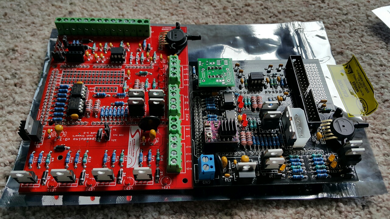
The physical connections will all be done with the red PCB shown above in post #64. Two of the edges will have screw terminals for the sensor/injector leads to be landed. In hindsight, I might should have gotten the Speeduino V0.4x board, instead of the V0.3.7 that I got...they're nearly identical, but the V0.4 has a 40 pin IDC instead of the screw terminals. Either way, I'm going to make an enclosure and jump the leads from the screw terminals to a DB terminal (probably 37) so I have a bulkhead with a removable harness, instead of a harness with an asswad of flying leads... make things much easier! In post #64 above, you can see on the left and top edges of the PCB where the screw terminals are to solder to the board and the sensor/injector leads are to be landed. Those are the ones that I will jump to a DB37.

Once complete, it will look something much like the one on the left here:
20160825_143856-resized-1280.jpg


The Arduino is mounted under the PCB on header pins (you can see them soldered around the perimeter of the resistors/ICs/MOSFETs in the center of the board). The one on the right above is the V0.4x.

I'm still on the fence about making a bench tester. MegaSquirt sells one for their package that they call a Stimulator...(MegaSquirt...Stimulator...I see what y'all did there! :lol:) I could build one for my Speeduino to do the same thing, and it would be incredibly handy to find issues before I connect it...but, I could also just get the sensors and connect them directly to the screw terminals and do pretty much the same thing. The only other thing I would need to do is connect it to a 12V source...the MegaSquirt Stimulator powers off of a 9V battery, but I don't know the circuitry in this one well enough yet to see that 9V will be enough...time will tell. They may have it split off such that it only needs a 5V reference for the Stimulator to function. I don't know the requirements of these drivers and MOFSETs just yet. So I'll either pair up a couple 9V batteries or get a handful of AA batteries in a couple 4 cell packs and do the same thing. I'd just need to build a square wave generator to make the RPM signal if I want it to think it's running. The reason I said I'm on the fence about it is that I think I'll only need it once...I'd hate to put that much time into something just for that...but on the other hand, I'd be able to learn exactly how the Tuner Studio works, get the IAC working properly, and make sure it all works well before it gets on the engine. So I think I might have just talked myself into making a bench tester. We'll see!
 
Can't say that I've ever seen a person get this adventurous with electronics under the hood of a Jeep before. Wow.
:beer:
:beer:
I've always been one of the "work harder, not smarter" class. Just ask @Croatan_Kid , he'll tell you. :lol: I actually had EFI under the hood of this one before, but it was basically a store-bought (actually a combination of scrap yard and eBay) setup. I had TPI on the 383 in a previous life. I'll dig through my Photobucket, I know I've got a pic of it somewhere...

Every since I went back to a carb for racing, I really, REALLY wanted EFI again. With what I've done to this Jeep at this point, there's no way I could go back to racing unless I wanted to run an open mod class, and I'd seriously be getting my ass handed to me...so EFI it is. Most places I've looked through the rule books don't allow aftermarket EFI at all. Only ones that do are open mod...but my frame/body modifications and choice of engine swap put me there anyway in most cases. I don't have the budget to build either a 500+ cubic inch N/A motor, or a high-winding 9000 RPM mill on boost or juice. So I've decided to go with what I've got and just farking have fun. And, the best way I could figure to go with what I've got is to DIY everything!

The only thing I'm afraid of with this project now is a) where exactly I'll mount the ECM, 2) building an enclosure to keep it safe from moisture, dirt and abuse, and d) still keeping it easily accessible for any potential future tune changes. I hear on the Speeduino web boards (not sure how true it is) that connecting with a long USB cable could introduce some noise into the signals...I don't know if that's because they're using a shitty cable, or if length truly does cause an issue... and that's what she said. :lol:
 
Just a thought.. if you have a spare output, you could control the bank selection of injectors... 4 from one fet and 4 from another by a complementary driven fet and achieve full sequential injection... Food for thought. Some of your project crosses over into my Jeep ECU project.. In some manner anyhow. As far as weather tightening, if you have no need to access the board physically, consider potting compound or conformal coating. I've got to check into it to recoat modified ecus. It's not really cheap from what I recall.. conformal spray is cheaper but doesn't provide the vibration absorption that potting does, and with sockets, that would be a point of concern unless secured together with fasteners.
 
Last edited:
Just a thought.. if you have a spare output, you could control the bank selection of injectors... 4 from one fet and 4 from another by a complementary driven fet and achieve full sequential injection... Food for thought. Some of your project crosses over into my Jeep ECU project.. In some manner anyhow. As far as weather tightening, if you have no need to access the board physically, consider potting compound or conformal coating. I've got to check into it to recoat modified ecus. It's not really cheap from what I recall.. conformal spray is cheaper but doesn't provide the vibration absorption that potting does, and with sockets, that would be a point of concern unless secured together with fasteners.
I've been reading your posts with quite a bit of interest. Id be incredibly interested to learn more about what you're saying about sequential injection. The board I'm using does have a prototype area, so it seems I could go full sequential without much problem. Looks like I've got some homework to do!
 
Just got a shipment notification from Mouser Electronics...I was scrolling down the list, doing my best impression of Homer Simpson:

maxresdefault.jpg


Line Number Mouser Part Number
Customer Part Number
Manufacturer Part Number
Description
Quantity Ordered Quantity Shipped
1
80-T356G106K035AT
KEMET Tantalum Capacitors - Solid Leaded
US HTS:8532210040 ECCN:EAR99 COO:MX 1 1
2
594-K224K20X7RF5UH5
Vishay Multilayer Ceramic Capacitors MLCC - Leaded
US HTS:8532240020 ECCN:EAR99 COO:CN 6 6
3
581-TAP476K006CCS
AVX Tantalum Capacitors - Solid Leaded
US HTS:8532210040 ECCN:EAR99 COO:SV 1 1
4
581-AR215F334K4R
AVX Multilayer Ceramic Capacitors MLCC - Leaded
US HTS:8532240060 ECCN:EAR99 COO:GB 1 1
5
80-C317C103K5R
KEMET Multilayer Ceramic Capacitors MLCC - Leaded
US HTS:8532240060 ECCN:EAR99 COO:MX 2 2
6
80-C330C105M5U
KEMET Multilayer Ceramic Capacitors MLCC - Leaded
US HTS:8532240060 ECCN:EAR99 COO:MX 3 3
7
80-C317C472K1R
KEMET Multilayer Ceramic Capacitors MLCC - Leaded
US HTS:8532240060 ECCN:EAR99 COO:MX 1 1
8
863-1N5919BRLG
ON Semi Zener Diodes
US HTS:8541100050 ECCN:EAR99 COO:CN 1 1
9
863-MBR150G
ON Semi Schottky Diodes & Rectifiers
US HTS:8541100080 ECCN:EAR99 COO:CN 4 4
10
859-LTL-4221N
LTL-4221N
Lite-On Standard LEDs - Through Hole
US HTS:8541402000 ECCN:EAR99 COO:TH 8 8
11
833-1N4004-TP
MCC Rectifiers
US HTS:8541100070 ECCN:EAR99 COO:CN 4 4
12
667-ERZ-V14D220
Panasonic Varistors
US HTS:8533404000 ECCN:EAR99 COO:JP 1 1
13
651-1935161
Phoenix Contact Fixed Terminal Blocks
US HTS:8536904000 ECCN:EAR99 COO:DE 14 14
14
571-28815452
TE Connectivity Headers & Wire Housings
US HTS:8536904000 ECCN:EAR99 COO:BR 5 5
15 571-41037410
4-103741-0
TE Connectivity Headers & Wire Housings
US HTS:8536694040 ECCN:EAR99 COO:MX 5 5
16
511-STP62NS04Z
STMicro MOSFET
US HTS:8541290095 ECCN:EAR99 COO:CN 8 8
17
603-MFR-25FBF52-10K
Yageo Metal Film Resistors - Through Hole
US HTS:8533210090 ECCN:EAR99 COO:TW 1 1
18
603-MFR-25FBF52-1K
Yageo Metal Film Resistors - Through Hole
US HTS:8533210090 ECCN:EAR99 COO:TW 15 15
19
279-LR1F680R
TE Connectivity Metal Film Resistors - Through Hole
US HTS:8533210090 ECCN:EAR99 COO:TH 4 4
20
279-LR1F470R
TE Connectivity Metal Film Resistors - Through Hole
US HTS:8533210090 ECCN:EAR99 COO:TH 6 6
21
603-MFR-25FBF52-2K49
Yageo Metal Film Resistors - Through Hole
US HTS:8533210090 ECCN:EAR99 COO:TW 7 7
22
279-H83K9BDA
TE Connectivity Metal Film Resistors - Through Hole
US HTS:8533210090 ECCN:EAR99 COO:IN 1 1
23
603-FMF-25FTF52100K
Yageo Metal Film Resistors - Through Hole
US HTS:8533210090 ECCN:EAR99 COO:TW 12 12
24 594-5083NW160R0J
Vishay Metal Film Resistors - Through Hole
US HTS:8533210090 ECCN:EAR99 COO:IN 4 4
25
926-LM2940T-5.0/NOPB
TI LDO Voltage Regulators
US HTS:8542390001 ECCN:EAR99 COO:MY 1 1
26
841-MPX4250AP
NXP Board Mount Pressure Sensors
US HTS:8542390001 ECCN:EAR99 COO:KR 1 1
27
579-TC4424EPA
Microchip Gate Drivers
US HTS:8542390001 ECCN:EAR99 COO:TH 2 2
28
576-SP721APP
Littelfuse ESD Suppressors / TVS Diodes
US HTS:8542390001 ECCN:EAR99 COO:pH 1 1
29
571-1-2199298-2
TE Connectivity IC & Component Sockets
US HTS:8536694040 ECCN:EAR99 COO:CN 3 3
30
80-C322C104K5R-TR
KEMET Multilayer Ceramic Capacitors MLCC - Leaded
US HTS:8532240060 ECCN:EAR99 COO:MX 7 7
31
603-RC0100FR-071KL
Yageo Thick Film Resistors - SMD
US HTS:8533210030 ECCN:EAR99 COO:TW 2 2
32
603-RC0805JR-0710KL
Yageo Thick Film Resistors - SMD
US HTS:8533210030 ECCN:EAR99 COO:TW 6 6
33
603-FMP200JR-52-4K7
Yageo Metal Film Resistors - Through Hole
US HTS:8533210090 ECCN:EAR99 COO:CN 2 2
34
710-885012207051
Wurth Multilayer Ceramic Capacitors MLCC - SMD/SMT
US HTS:8532240020 ECCN:EAR99 COO:TW 1 1
35
80-C0805C102K5R
KEMET Multilayer Ceramic Capacitors MLCC - SMD/SMT
US HTS:8532240020 ECCN:EAR99 COO:MX 2 2
36
77-VJ0805V104ZXACBC
Vishay Multilayer Ceramic Capacitors MLCC - SMD/SMT
US HTS:8532240020 ECCN:EAR99 COO:CN 1 1
37
700-MAX9926UAEET
Maxim Integrated Sensor Interface
US HTS:8542390001 ECCN:EAR99 COO:TH 1 1
38
855-M20-9990445
Harwin Headers & Wire Housings
US HTS:8536694040 ECCN:EAR99 COO:TW 2 2
39
80-C0805C103K5RAUTO
KEMET Multilayer Ceramic Capacitors MLCC - SMD/SMT
US HTS:8532240020 ECCN:EAR99 1 0


....Til I got down to that last line item. Then it was:

20twio.jpg


One damn capacitor backordered for 3 weeks?? Meh...not like it's going to hold me up any at this point. :rolleyes: Still a pain in the asses though.

EDIT: Belay that...just checked the page, and now it has an estimated ship date of tomorrow. I guess they got a better date from the original estimate of the 27th? That was a quick update. Still won't hold me up though!
 
Last edited:
I did make a sim board for the Jeep SBEC but I can probably retweak it for whatever signals you need. It seems useful to see injector PW at various conditions.. Plus you can see if working. this is what i was talking about to go fully sequential if you have an extra output and can presently control half the injectors (semi-sequential). The output provides a way to toggle power between bank 1 and 2 from one output. you can use two seperate outputs instead of the extra transistor as an inverter. Feel free to substitute FETs instead of BJTs. excuse my mspaint art.. i dont have any schematic soft on here yet.
inj driver.png
 
That's slick! So if I found a way to run that off of an extra output, I could toggle between each pair of injectors running off of each driver (I'll have 4 drivers with this board)...am I interpreting correctly?

excuse my mspaint art.. i dont have any schematic soft on here yet.
View attachment 269771

Yeah, you've gotta touch up those skillz, man. :lol: Please, if I tried drawing electrical schematics on ms paint, it would look like my 13 month old daughter drew it. I do well enough (barely) with a pencil and paper.

That's definitely got me thinking, though...the board does have a proto area. I'll have to see if I can figure out where to run something like that in the firmware. Thanks for that!
 
Back
Top