Bent Fab CH2

Mac5005

Well-Known Member
Joined
Oct 19, 2005
Location
Rocky Mount
I’m building a bent fab ch2 for one of my wheeling buddies Steve. I’ll be documenting what I can here, Steve will handle all the FB posts haha.
Steve had an older blue torch 4 seat chassis that he parted out and is swapping most of the parts to this chassis.

Quick rundown:
Bent Fab CH2 chassis kit
D60/14B, 6.0/350/4sp atlas, ORI’s.
 
The chassis arrives in a 4 x 8 pallet/box.

0CDE39E2-7F0D-4D94-9A2F-189B8D0D7DC2.jpeg

F270F91D-1B30-4D92-8A8D-B357E72E23B7.jpeg
 
Unpacking and laying out the tubes was fairly straightforward. Cleaned and degreased the tubing at this point. The tubes are all laser etched to identify each one.
Once we knew we weren’t missing anything we started with a couple main pieces on the frame table.

This was more to just see how well initially all the pieces fit and how much squaring it was going to need based on the locating holes and the fixtures from bent fab.

AAF1E6BB-996E-4D92-8BFA-639329AE715B.jpeg
C3A0FECB-A045-48E6-A966-2FAC9C633A42.jpeg
 
After getting 70% of all the tubes clamped, strapped, and in the fixtures, we soon realized that the bottom two rocker rails on each side need to be in critical alignment.
The fixture is decent, but could definitely be improved on the front end to next better assembly times.
The fixture holds the horizontal front and rear seat tubes, dash tube, rear harness tube, and horizontal roof tubes.
The fixture does very little to align the front/rear running tube work.

The design of the bent rocker tube work means that any small change in front to rear positioning changes the entire chassis completely.

more laser etching to locate these critical tubes would make the assembly much faster.
Without clear defined measurements on some locations, it requires some definite skills, knowledge, and tools to figure out where exactly the tubes are supposed to be.

this is my main complaint so far. There is a definite lack of information provided from bent fab. A PDF of critical dimensions, or 4/6 more laser etch marks on 2 tubes would literally save 3-4 hours of headache.

all that said, between Steve, my dad Russ, my wife sam, and I, we were able to get the chassis from the belt line down square and flat, and all tubes in their correct locations.


33BED7B9-CB2D-40E5-A4D2-2F6A34E96ADC.jpeg
B6063FF3-6E3F-4035-92B5-508D78FA7044.jpeg
514673FA-D9CF-4FB0-A8F9-C69DE039C77D.jpeg
630C326B-D500-47A3-B48D-C2671C2F3D11.jpeg
2A777E1C-2135-41E2-B48B-9FB631A4AB51.jpeg
 

Attachments

  • A51D8B0C-33E3-499D-B22A-B1DC0B41FE97.jpeg
    A51D8B0C-33E3-499D-B22A-B1DC0B41FE97.jpeg
    150.5 KB · Views: 176
A countless number of tubes are needed to be initially installed to check for overall shape and squareness etc.

Due to the tubes being laser cut and notched if something is wrong it is very apparent. The laser work is spot on, and when things are in the correct place, the copes are perfect.
A lot of this process is the “chicken or the egg”.
Meaning install 6 tubes, check squareness, tack, remove 6 tubes, tack, reinstall 4 tubes, check, tack etc etc etc.

We definitely have to have a lot of tubing installed to accurately check overall placement and locations.

Tim @ Bent Fab has a YouTube video of him “assembling” a chassis in 2 hrs.
While I completely agree that’s entirely possible, it’s highly unlikely.

We spend double that time assembling and removing, moving, then reassembling. This was to get all the tube joints 100% and everything located correctly.

83E483BF-9F05-4040-BF27-D08DAB91FAE6.jpeg
9ED763E2-ADA8-4EA4-AC52-682605C3BBFB.jpeg
CC4CBFF5-5AF0-4A14-9618-88FBE5E5CBD2.jpeg
5BD2492E-FAF5-45BB-9784-8869071FEB52.jpeg
2D52DBC4-FB5C-4352-9596-92AFEA7ED7A5.jpeg
CEE2F318-06C5-4933-8C04-1D458C50D7F9.jpeg
EA39798B-8771-4508-AE1C-E844E04B9E66.jpeg
62CEE449-D12D-47A6-A426-E43898E55047.jpeg
234C8F37-EC31-43EF-99D9-F9048B2A65B9.jpeg
865DCA9E-4C5E-4816-A209-C90A93E2BA78.jpeg
BD09D6CC-BE7B-44C9-932C-A9D74F176303.jpeg
 
As of this morning we have the main tubes in and welded for nearly everything below the belt line.
Several of these nodes have cross tubes and diagonals that overlap the welds of other tubes.

I went ahead and welded these main tubes so that the additional diagonals do not cover up an unwelded notch.

today we will be working on getting the roof on, removing the “fixture”, adding all the support tubes and diagonals back in.

Hopefully if we get all that done, we will be flipping the chassis over, to then put the belly on.

Tim @ Bent Fab has a FB group for chassis support with albums for assembly. However some of the laser etch marks and locating holes he references in thes pictures are different on the production chassis.

honest assessment so far, nice kit, nice bends and super nice laser copes on the tubing. Needs more laser etching or turn the quality up on the etching. Or more locating holes to denote locations better. PDF of some basic critical dimensions would be easy to pull from cad file and send with chassis order. Need to have your brain on to get this thing lined up and square. This would eliminate some of the need to have 75% of the tubes sat in place and clamped before the first tack goes in.
 
Last edited:
A note for anyone wanting to do this:

tubes #17/17M need to go in before the rear shoulder tube #26 but the fixture is completely in the way to do so.

you must cut a complete ear off one of the copes at one of the ends of #17 to allow clearance to install, and then weld this ear back on. Lol.

back to welding.... update fixture is out, two a pillar gusset tubes to install, some more welds, and it’s time to flip to put the belly on.
Shooting to have this done and fully welded today.


E6405003-ACDB-44AF-8FD2-4C9323338183.jpeg
8C51597C-5343-424E-81F5-3945877A5E02.jpeg
 
Last edited:
Some grinding required to get the lower belly on. This was because all of the upper was fully welded. Had to grind some tubes to make clearance for the welds. Still way better than doing all the copes by hand.

the video was Steve trying first fitment earlier today.

even got my wife sam to help weld some on the front. She also helped a ton with fit up, layout, and getting everything in the right places.
 
I’ve always liked Tim’s chassis, they’re a clean design. Good luck with the build!
 
I’ve always liked Tim’s chassis, they’re a clean design. Good luck with the build!
Thanks Danny. It’s a cool design. The kicked up rocker and simple design work well. It’s a nice package. There isn’t really any wasted tubes. It’s a little tight for me, but fits Steve and sam very well. We will know more today about how far we can lower the seat and still have tcase clearance. It’ll be interesting to see the driver footwell clearance.
 
Last edited:
Damn, let's build a buggy THIS WEEKEND!
Haha exactly. I definitely see the value in a prenotched/bent buggy in a box kit for sure.

Someone could build their own buggy without a tubing bender, bendtech, or notcher. That could potentially be the same costs as one of these kits, not including the time savings of having it together in a weekend vs much much longer.
 
I’ve looked and thought but don’t have an answer....

why is that 5 gallon bucket hoisted to the top of the gantry? Maybe to get the hanging chains out of the way? :D
Yep, it’s to keep the chains up and out of the way between uses

I keep wondering when all the non buggy questions about stuff in the background would start happening. Haha. You win.
 
So which Lincoln is that? Really cool you put that thing together in a weekend.
 
So which Lincoln is that? Really cool you put that thing together in a weekend.

lincoln powermig 210 mp with .030” and 75/25. I sold my older Millermatic 212 (non autoset transformer machine) a couple years back and bought this one the next day.
It runs circles around the Miller. Welds better, more capability and more consistent.
I always worried about how the inverter would perform and it’s consistency cold/hot.
It works. Doesn’t miss a beat.

The fact that I can set wfs run in and tune the inductance to fine tune how I want my puddle to look, and how it freezes, wets the toes, and helps with convexity/concavity is practically revolutionary.
I tried to see if I could hit duty cycle while running .030” and .035” hardwire mig, not happening. It just keeps welding.
I’ve also had great results with the Lincoln spool gun on an aluminum rack I built.
I haven’t tigged with it, as I have a separate water cooled tig setup.
 
So today Steve and I got a lot done, but don’t have much to show for it. Haha.
First we started with cleaning up.
Cleaned his 6.0 up with degreaser and pressure washer. Then we drug one of my dads th350 out and pulled the converter and drained all the oil out. Next we cleaned up Steve’s atlas.
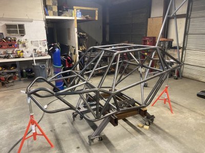
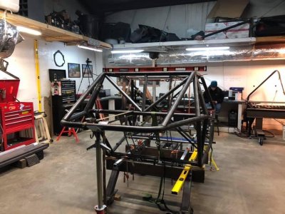
Once everything was cleaned up, we got the chassis back up in the air and got the frame table back under it, to hold the belly at 20”.

I think the belly will eventually end up around 18” but I built the frame stand/table to be 20” to build from.

After cleaning and reorganizing and putting stuff away where it belongs, and just less clutter of parts strewn everywhere, we slid the trans and case into the belly.

this required us bolting the bent fab th350/atlas billet adapter onto the back of the 350.

next was shoe horning the 6.0 into the front of the chassis, and up onto the legs of the front of the frame table/stand.
Everything we read , says the engine has to come out the bottom, so we installed it that way.

at this point we wanted to bolt the drivetrain together and start looking at mounting it all.

I was wrong. There it is, I admit it, it’s happened before, it’ll happen again.

in my quick thinking and bench racing over the last couple weeks, I said:
“No need to change the atlas input from 32 spline to 27 spline yet, 32 is greater than 27, the atlas input should just slide over the 27 spline 350 output no issue. As long as we have the correct adapter, we can mock it up!!”
I was completely wrong!!!! It won’t go in, no matter how much wiggling and aligning you do.

next, the 350 we were using for mock up has an extra deep pan, that won’t work either. Raises the trans up too much and puts the case at a weird angle to the belly and bottom of the seat tubes.

So no more mocking up drivetrain until we get the atlas input swapped, and the a standard pan on the 350.

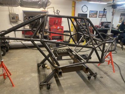
good news is, the 6.0 will come out of the top of the engine area, it’s tight but it fits out the top. This is without the front X tubes (35,36,37) in place.

looks like we will fab a removable front X brace so the motor can come out the top.

it was bugging me that everytime you want to pull the engine, you have to pull the front axle out.

Probably isn’t a big deal in all reality, unless changing the trans or converter would mean pulling the engine, and in turn pulling the front axle. That would be a large snowball.

at this point we started looking at link mounts and all from bent fab.
Steve purchased the modular rear link kit, which has wayyyy better geometry than the basic kit, and is the same mounts Tim @ Bent fab uses for his trailing arms.

so at that point progress on drivetrain mounting was halted, we thought we would bolt these assemblies together and tack them up ready for install.

this is when we discovered, that all Tim’s plasma cut holes are all under size. Looking at the holes, he hit several with some type of wheel, as 1/4 to 1/2 the plasma cut edge shows signs of drilling/cutting etc. However a 3/4” bolt will not fit through the holes.

This is 56 or so holes through all the tabs, brackets, and reinforcing plates need to be drilled out to 3/4 to allow the bolts to pass thru.

so we checked some more 3/8 plasma holes for the motor mount package, and half the holes are drilled for the correct size (10mm for head mounting) yet the 3/8 plasma holes barely allow a 5/16 bolt to pass thru. 😠

drilling a plasma cut hole is terrible. The plasma cutting operation leaves an oxide layer that is also hardened due to the extreme heat (45000-55000°F). This will kill a high speed steel or TiN coated HSS bit in seconds. The oxide and plasma hardened area is harder that the HSS.

Now when I cut holes on my crossfire pro table, I cut a test hole in scrap, check for bolt pass thru, and adjust my hole sizing before I cut the final part. OR I cut a .250” hole for location knowing I have to drill out larger. Typically I then use a stone wheel in a die grinder to remove just tiny amount of this hardened area and then hit with normal HSS or step bits.

Another option is to use a drill that is harder than the oxide and heat hardened area. Carbide.
So Steve went a grabbed a 3/4” masonry carbide tipped drill, chucked it up in the drill press and started drilling. I touched up the carbide to bring the OD down a little, and to increase the rake on the carbide cutting edge. It works, and makes a nice hole, but takes a lot of cutting pressure.
Going to take a while to do all 56ish remaining holes.
It’s also such a pain bc the holes are currently about the same size as the minor diameter of the 3/4” thread on the bolts. So it’s not like we have to remove a lot of material, but it’s all that oxide and hardened area.
It would be easier to take the hole from 1/8 or 1/4 up to 3/4, than what we need to do.
Steve is maybe calling Tim in the morning when cools off some haha.

I didn’t take many pictures today as I was tired and sore, and was focused on what we needed to accomplish. I’ll try to not let it happen again.

C2F64E01-1A5F-498C-97AD-8D8B097A4E10.jpeg
1F2DDCAE-26DD-4A6A-96A1-DEFF67E00872.jpeg
91DB89E1-485D-450E-8EC3-EDBCD4232C4C.jpeg
C4755F7F-11E0-464A-ABEA-3039BE7F0104.jpeg
6CDBE892-5E42-47D5-835D-4D6A63A205C2.jpeg


we also discovered that the poly bushings as part of the kits to mount the motor and tcase use a 1/2” bolt but have tabs with 5/8” holes. :facepalm: Looks like I’ll have to fire up the crossfire pro, and make new tabs for these with the correct hole sizes.
D68E6304-7712-48DD-8F06-CB4258EBCD10.jpeg
179CE017-5567-44C3-BAD8-2AC8E732F5A6.jpeg
032E8E9B-8EB1-4C05-B624-943D5AEA512C.jpeg
DBE062F8-BAEC-4107-B06D-E60ABF0A326B.jpeg
 
lincoln powermig 210 mp with .030” and 75/25. I sold my older Millermatic 212 (non autoset transformer machine) a couple years back and bought this one the next day.
It runs circles around the Miller. Welds better, more capability and more consistent.
I always worried about how the inverter would perform and it’s consistency cold/hot.
It works. Doesn’t miss a beat.

The fact that I can set wfs run in and tune the inductance to fine tune how I want my puddle to look, and how it freezes, wets the toes, and helps with convexity/concavity is practically revolutionary.
I tried to see if I could hit duty cycle while running .030” and .035” hardwire mig, not happening. It just keeps welding.
I’ve also had great results with the Lincoln spool gun on an aluminum rack I built.
I haven’t tigged with it, as I have a separate water cooled tig setup.
I have the same welder. I struggle with it so I guess it's me and not it. I thought I was reaching the end of duty cycle but I guess it was the end of RQ cycle! lol At least it's good to know that it's a good machine.
 
Back
Top