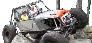
Bent Fab CH2

In other news, we got the input on the 4 spd atlas swapped from the 32spine to 27 spline. This was ridiculously easy, and again I didn’t take any pics.

It’s as simple as unbolt the front planetary housing from the atlas, remove the front seal retainer, two snap rings, and pull the input out of the planetary.

Install needle bearings into new input gear, slide this back into the planetary carrier with new thrust washers, slide this back into the housing. Then reinstall the 2 snap rings, one bearing to case, one input to bearing, reinstall the seal housing and bolt the front “4spd” planetary housing back onto the atlas.

hoping to have the atlas and th350 back into the belly tomorrow night.

just have to keep reminding myself to stop working and take more pics.
 
my complaint is that he cut the holes, and cleaned them up 15 to 20% of the thickness by some means of cutting. And after doing such the holes are still .010” to .020” undersize, while some holes are completely drilled/milled and fit their fasteners, while some have. .610” hole for a 1/2” bolt.
There's no reason he can't cut em 0.505"-0.530" pretty consistently with a friggin CNC anything (plasma/waterjet/laser/heck even oxy torch) on material that thin.
 
3/4" drill should be plugging along around 400-500rpm (80-100SFM) in average steel. Throw in some rough, hard edge and you'll want to slow it WAAAY down and it'll still probably die, just less fast :D
Most the stuff I was drilling out was 1/2" and it wasn't my tooling, it was works.
There's no reason he can't cut em 0.505"-0.530" pretty consistently with a friggin CNC anything (plasma/waterjet/laser/heck even oxy torch) on material that thin.
This, in 3/16 it's pretty easy to get the holes consistent. I can get the OG crossfire to do it for a good amount of time.
 
Really cool to see one of these brands of chassis come together local. I do hate to hear of the detail issues though. I’ve always felt he demanded a pretty high premium for what the product is so I’d expect a little more attention to detail.

I agree. Early on his chassis looked awesome and where fairly cheap comparatively. When he released the DIY kits, I thought they would be cheaper. Still cheaper than having someone build a chassis for you, but I wouldnt have expected the issues they are seeing.
 
Got the deep pan removed from my mock up 350, and a standard depth pan installed.
This way I could get both tcase and trans in the belly with hopes of getting them bolted together in order to get the motor back in and start looking at mounts.

this is important so that we can start looking at link/driveline placement, headers and exhaust, as well as seat position.

got the case and trans in the belly and slid together but cannot bolt the 350 to the 4 speed using the BFR supplied adapter.


8A8BDB90-ECB0-4829-8AFA-73A5944FE373.jpeg


0D9AB305-25E3-4F5D-BE4A-57040BCBD18F.jpeg


70214145-85E3-40DE-8BC5-027983859B1A.jpeg


90ADC9D9-E04D-4211-93CB-8928E84920F6.jpeg


43BB218C-BF8A-47CB-89B6-CFC3A2A70D02.jpeg


F4510EB5-C18D-40BB-905A-0DF4043057DD.jpeg

In those pictures, inside the holes that are supposed to be used to bolt to the atlas,
Are the heads of the SHCS that bolt the 4spd planetary to the front of the atlas itself.

the planetary box of the 4spd is not clockable. Only six holes in the main atlas case itself.
So it looks like tomorrow night, drivetrain goes back onto the table so I can drill 6 new holes in the adapter.
Anyone have dimensions or a file on an atlas d300 clocking ring or pattern lol :)
 
Last edited by a moderator:
Got the deep pan removed from my mock up 350, and a standard depth pan installed.
This way I could get both tcase and trans in the belly with hopes of getting them bolted together in order to get the motor back in and start looking at mounts.

this is important so that we can start looking at link/driveline placement, headers and exhaust, as well as seat position.

got the case and trans in the belly and slid together but cannot bolt the 350 to the 4 speed using the BFR supplied adapter.


View attachment 339169View attachment 339170View attachment 339171View attachment 339172View attachment 339173View attachment 339174
In those pictures, inside the holes that are supposed to be used to bolt to the atlas,
Are the heads of the SHCS that bolt the 4spd planetary to the front of the atlas itself.

the planetary box of the 4spd is not clockable. Only six holes in the main atlas case itself.
So it looks like tomorrow night, drivetrain goes back onto the table so I can drill 6 new holes in the adapter.
Anyone have dimensions or a file on an atlas d300 clocking ring or pattern lol :)

i have the d300 file. I think in DXF but will need to find it.
 
So I think I speak for many when I say we want to know what the result was for the hole discrepancy on the tabs, that were paid extra for to save time? Was money offered back, correct brackets offered, or was the statement about the zinc coating all that was given? Pretty disappointing service if so, mistakes happen but if no effort was put into making that right, that’s pretty telling.
 
So I think I speak for many when I say we want to know what the result was for the hole discrepancy on the tabs, that were paid extra for to save time? Was money offered back, correct brackets offered, or was the statement about the zinc coating all that was given? Pretty disappointing service if so, mistakes happen but if no effort was put into making that right, that’s pretty telling.
That’s an excellent question, and I’m so glad you asked that question. It brings up an important aspect, and I’m really happy you brought this up.
 
A couple random pics from last night.

initally we were shooting for 18” belly at 112”ish wheelbase on the 43” Mickey’s with 7up on the 14” ORI’s.
The rear is no issue and no potential interference anywhere.

once we got the front axle under the chassis, it became immediately apparent we needed to push the front axle forward another 6-7 inches to get clearance between the front driveshaft/pinion and crank/water pump/starter.

This also means the rear needs to move forward a few inches to keep the wheel base from growing.

after getting the axle at full bump, we found that the 7” uptravel with 18” belly height just wasn’t going to work.

so we raised the belly back up to 20” and this created a ton more room up front. Mainly for the pass side upper link.
Our pvc mock up links showed us that for now this is the winning combo with this chassis and front axle.
A driver side front diff would have far better clearance due to the pinion offset, as would a pass drop low pinion.

once the front axle location was confirmed, now we are moving the rear axle forward to get back to a 114/115” wheelbase.
This also helps to get the front and rear links closer to the same length-ish.
FFBCABD9-466E-4CFB-B095-686E6F169610.jpeg
0FE62238-85BD-4573-B555-FF9068A36875.jpeg
448EFC3B-AF6A-46B4-9E14-F0EAE98A408C.jpeg
406F148D-9651-47AD-8ABD-E9BC5C383251.jpeg
39F26479-42FE-4536-B4D1-CAF0A8BE95CB.jpeg
DCA28193-9B32-463A-972D-5A49B91BA7E8.jpeg
E9AF0452-DC89-4048-B1D0-6C07222D2BE6.jpeg
56D9AA08-1EDF-4B80-8FEC-9C72DC531691.jpeg
 
I don't know if it's been said yet or not but the answer to your problem is a carbide 3/4 endmill. Takes about 1 second to fix those holes. I'll mail y'all one if you're still dicking with those holes. Frustrating to see something like that slow you down so much you'd about be done by now at the pace you going.
Thanks for the offer Braxton I really appreciate that. No we are not messing with the holes any longer, I should have some pics and explanations of our solution by the end of the weekend.
 
After updating fire control and fusion360 :facepalm: , finally got to making some cuts. Also huge thanks to Kevin, my dad Russ @moldman05, Steve, and my wife Sam for all the help today while I was working on the laptop.
Kevin, Steve, and my dad focused on getting the rear axle clean. They plasma cut the brackets off, and went after the remnants with zip wheels, hard wheels, and finished with flap wheels.
Steve, my dad, and sam worked on the motor mounts and getting them prepped and tacked.

Then sam fully tig welded them for us.

so as of tonight, motor mounts are fully done. Front lower link tabs are done, just need to be prepped and tacked in.
Idea is solidified for the front upper tabs, just need to draw them up in cad and print them on the cross fire.

hopefully will have all front links tabs tacked in place, front links cut and tacked tomorrow.

I didn’t get many pics today, but I’ll try to get some from my dad and Steve.

just a couple of some tabs and gussets I cut on the crossfire vs BFR stuff it’s replacing.
 
Back
Top