D-6

This is super cute and all but the 30k in special machining to have all those pockets and fillets cut will be fun. Ever ran a Bridgeport or Haas milling center...?

Next up formed carbon monocoque upper arms and titanium wishbone:popcorn:

Sold that there's a meme for everything now

download.jpeg
 
Nice observation guys. I calculated the high number on that 31 degrees. I was glad to see it below 31. I have to measure these 3 parts to get it dialed. Should be within range. Thanks for love Fella's.

FB_IMG_1597893795574.jpg


FB_IMG_1597893767917.jpg


FB_IMG_1597893763189.jpg
 
I still want to know what is the driveshaft plunge on that rear unit...

Also, how do you calculate a high number on a CV angle while you got everything plotted in CAD ? I thought you measured it through the software, not like you had to pull your calculator or anything...
 
If all you have to do is draw some shit in MS paint to be considered a build thread, I should have started my own years ago.

No kidding. This whole thread is the most aggravating thing ever. I understand you don’t build a house without a plan but this is absurd IMO. Specially when he says things like “had trouble fitting the shocks because...”

No you didn’t, you’re not building anything yet so you’re not having trouble, you’re changing the plan. How bout an update with some hard parts arriving, some metal going together, some stickers being applied. The important things.
 
The front end geometry has evolved into 19.25 inches of vertical wheel travel, with the company of 7 degrees caster angle. The IFS suspension is flexed to the max with the current geometry using the upper control arms. The driver side CV angle is 26.5 degrees, and the passenger side is less. The differential had to be lowered from it's previous position in order to keep previous (same) wheel travel. The Camber angle is 0 degrees at ride height, and has 12.26 degrees of fluctuation total. 7.43 degrees of negative camber at full bump, and 4.83 degrees of positive camber at full droop. There are also some photos of the passenger tire completing a 40 degree right turn at full bump. Also, the rear end is flexed some, but it has plenty more movement.

IFS 17.jpg


IFS 19.jpg


IFS 20.jpg


IFS 21.jpg


IFS 22.jpg


IFS 23.jpg


IFS 24.jpg


flex 1.jpg


flex 2.jpg


flex 3.jpg


flex 4.jpg


flex 5.jpg


flex 6.jpg


flex 7.jpg


flex 8.jpg
 
The front end geometry has evolved into 19.25 inches of vertical wheel travel, with the company of 7 degrees caster angle. The IFS suspension is flexed to the max with the current geometry using the upper control arms. The driver side CV angle is 26.5 degrees, and the passenger side is less. The differential had to be lowered from it's previous position in order to keep previous (same) wheel travel. The Camber angle is 0 degrees at ride height, and has 12.26 degrees of fluctuation total. 7.43 degrees of negative camber at full bump, and 4.83 degrees of positive camber at full droop. There are also some photos of the passenger tire completing a 40 degree right turn at full bump. Also, the rear end is flexed some, but it has plenty more movement.

View attachment 324973

View attachment 324974

View attachment 324975

View attachment 324976

View attachment 324977

View attachment 324978

View attachment 324979

View attachment 324980

View attachment 324981

View attachment 324982

View attachment 324983

View attachment 324984

View attachment 324985

View attachment 324986

View attachment 324987
These renders don't have an actual CV unit in them. Is there a model you are assuming will fit?
What are the cylinders sticking out of teh differential - is that a flange the end of the CV body bolts onto, or is that the cup that the actual CV joint slips into? If its the former, then your model isn't accountin gfor the horizontal space taken up by the body and flange, which puts the actual angles at a differen hinge point than the LCAs.
 
Wait wait wait...Is this an RC car?
 
These renders don't have an actual CV unit in them. Is there a model you are assuming will fit?
What are the cylinders sticking out of teh differential - is that a flange the end of the CV body bolts onto, or is that the cup that the actual CV joint slips into? If its the former, then your model isn't accountin gfor the horizontal space taken up by the body and flange, which puts the actual angles at a differen hinge point than the LCAs.

Actually, as I was reading your questions, I was thinking I should be diligent with answering them. It is extremely important that I execute the measurements and angles correctly on this front end. I mean, quite literally, if I'm doing something wrong here, I have to stop and make it right. Some or most of the questions, and remarks towards this car I may end up ignoring, but if I'm doing something wrong here I don't mind hashing it out til it's right. What I've done is I have called RCV and gathered the dimensions for the CV, and the RCV (45 spline outer, 40 spline inner) Big bell active out at the hub.

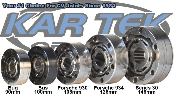
What I have here, is a series 30 (40 spline plunging) CV attached to the correct axle stub flange width of the narrow Spider Trax IFS housing. I'm under the impression that we're good, but I don't need to leave anything to chance on these CV angles.

My axle plunge allowance is 1.3125 inches, and I am using a total of 0.75 inches per only the CV connected the to the differential. The RCV big bell is fixed, it has no plunge.

cv dimensions.jpg


cv half shaft 1.jpg


cv half shaft 2.jpg


cv half shaft 5.jpg


cv half shaft 6.jpg


cv half shaft 7.jpg


cv half shaft 8.jpg
 
Last edited:
Super excited about the development on the D-6. Changed some of the tube work in the rear.

33 gallon fuel cell added. I feel like I could double the fuel capacity with no issue. There is a number of ways to go about doing it, aside from stacking an auxiliary desert tank on top of the existing one. Surely, an option I'm going to look at later for lots of miles on the race course without stopping for gas. An auxiliary tank like that would be simply gravity fed with a small hose. An auxiliary tank like that, above the main tank would require an external tube cage around it. I feel like the sky is the limit on options there.

At some point over the years, I've acquired the taste for a sump tank. I may have plenty of room for a 5 to 10 gallon sump tank under the driver seat. In a perfect world, the idea would be 1 or 2 fuel tanks, feeding the sump tank where the fuel is picked up. Incorporating the feed fitting to enter the sump tank at the top\forward side of the tank under the seat. That way every time the car is going up hill, it always has a full 5 gallon reservoir to pull from.

I feel like this chassis is smaller than it looks. It will get thinner at the bottom, so I may have a heavy eye on fuel capacity, and where I can get it from.

My goal today was to get more of the chassis and parts lay out done to get a visual. I think I succeeded with the main fuel cell, and the spare tire.

It's been a long day and I'm probably rambling, but I was pushing to post an update for yours and my own visual purposes, because I'll leave for Kentucky/West Virginia mountains for the next week or so without internet and a computer. I don't know, I may put my little brother in the drivers seat of my Dodge at 6 am so I can stay up and mount the radiator, transmission cooler, and the oil cooler on this thing tonight to get it posted.

Before I forget.... I'm working all around dimensions on seating position. I measured one of my late 80's Toyota trucks. Seat slid all the way back, with the dimensions on the firewall where the gas pedal is floor boarded. Looks like everything seating position wise is within range of optimizing. Like, within an inch or 3 but it looks good to get right.

chassis 1.jpg


chassis 2.jpg


chassis 3.jpg


chassis 4.jpg


chassis 5.jpg


chassis 6.jpg


chassis 7.jpg


chassis 8.jpg
 
Last edited:
Ready to see how comfortable the driver will be in this, how tall are you? It looks cramped as hell and there's nothing in the cockpit yet. This is being built for KOH/long races?
 
Back
Top