biggun68
Well-Known Member
- Joined
- Oct 27, 2010
- Location
- Mooresville

Any tig weld should maintain a fluid transition accross the weld pool. The stack of dimes "look" should only be created by the addition of filler material added to the weld pool. In the case of aluminum this is done on the leading edge. As the torch passes throught this material is should then be "wetted out creating a uniform bead. By maintaning the weld pool and only adding to the leading edge penetration is maintained without excessive burn through. Aluminum naturally will "suck" the material to the center of the pool, STEEL, STAINLESS and almost any other material does not react this way. When welding these material the filler shoud be added to the center of the weld pool. Penetration is achieved strictly by the depth of molten metal like aluminum but the filler does not flow the same. Adding behind center usually results in the arc cutting the filler rather than it reaching the melting point and completely being absorbed "also known as becoming part of the weld solution". This is where uniform fusion takes place. Adding the filler to the leading edge causes shallow penetration and a host of poor fusion problems. When manually pulsing or automatic forward progress and the addition of filler should only be made during "on time." This can be timed so that filler is added near its peak for maximun dillution of the filler into the parent material. This gives the best fusion. As the level of energy ramps down slight forward progress is acceptable but never beyond what the setting allows for a continuos molten pool. This whole process can be slowed down in a manual pulse where you can litterally add each "dime" however the bead should be uniform a continuous. If you can measure dicontinuity greater than a 32 of an inch across a weld section or catch a finger nail or pick at any piont its a flaw and an area of poor fusion. IN SHORT in a destructive plate test it will rip like a zipper. Test and weld inspection and the AWS welding code spells it out pretty clear.
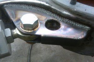
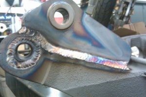
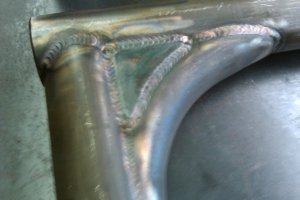
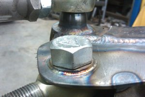
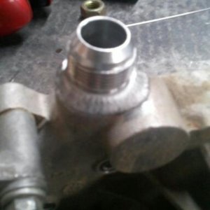
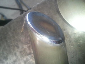
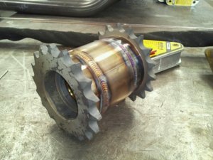
You are right. I can't argue with that. My root pass on those welds was done exactly as you described it should be done. What you are seeing in those pictures of the alternator bracket were all done as a root pass with filler and a cap pass using the pedal to ramp the heat up and down to flow the puddle with smooth forward motion, no filler added. I was showing Chad (95yjjeep) how you can get different effect/looks with amperage control and travel speed vs. adding filler. They just happened to look pretty decent when I was finished so I figured I'd update the thread.View attachment 44632
Any tig weld should maintain a fluid transition accross the weld pool. The stack of dimes "look" should only be created by the addition of filler material added to the weld pool. In the case of aluminum this is done on the leading edge. As the torch passes throught this material is should then be "wetted out creating a uniform bead. By maintaning the weld pool and only adding to the leading edge penetration is maintained without excessive burn through. Aluminum naturally will "suck" the material to the center of the pool, STEEL, STAINLESS and almost any other material does not react this way. When welding these material the filler shoud be added to the center of the weld pool. Penetration is achieved strictly by the depth of molten metal like aluminum but the filler does not flow the same. Adding behind center usually results in the arc cutting the filler rather than it reaching the melting point and completely being absorbed "also known as becoming part of the weld solution". This is where uniform fusion takes place. Adding the filler to the leading edge causes shallow penetration and a host of poor fusion problems. When manually pulsing or automatic forward progress and the addition of filler should only be made during "on time." This can be timed so that filler is added near its peak for maximun dillution of the filler into the parent material. This gives the best fusion. As the level of energy ramps down slight forward progress is acceptable but never beyond what the setting allows for a continuos molten pool. This whole process can be slowed down in a manual pulse where you can litterally add each "dime" however the bead should be uniform a continuous. If you can measure dicontinuity greater than a 32 of an inch across a weld section or catch a finger nail or pick at any piont its a flaw and an area of poor fusion. IN SHORT in a destructive plate test it will rip like a zipper. Test and weld inspection and the AWS welding code spells it out pretty clear.
All welds are stronger when the weld pool remains as uniform as possible. Any irregularity introduces stress risers into a weldment. Welds will always tend to be either stronger, weaker, more or less ductile, elastic or dense than the parent materials. This is why full dillution and the most uniform penetration and bead characteristics is desired. Welding chromoly is a good example of how weld pools react on the more extreme end of alloy characteristics. Welded with the incorrect filler and heat results in weld cracks and imediate failure (again extreme example).So to sum up what you said basically for a stronger weld you want something similar to the pic you posted rather than a stack of dimes?
wasn't really refering to any one pic or post. I thought it was a good educational moment. I get alittle wound up about welding. guess every body can tell by now. I just hope everyone doesn't have the impression that every weld I lay down is laboratory correct or that I think they are. They aren't but I have a pretty good base of knowledge. This is why I strive to work on it often. For me understanding the science made me a better welder rather than all the practice in the world. I enjoy being able to share some knowledge on the subject.You are right. I can't argue with that. My root pass on those welds was done exactly as you described it should be done. What you are seeing in those pictures of the alternator bracket were all done as a root pass with filler and a cap pass using the pedal to ramp the heat up and down to flow the puddle with smooth forward motion, no filler added. I was showing Chad (95yjjeep) how you can get different effect/looks with amperage control and travel speed vs. adding filler. They just happened to look pretty decent when I was finished so I figured I'd update the thread.