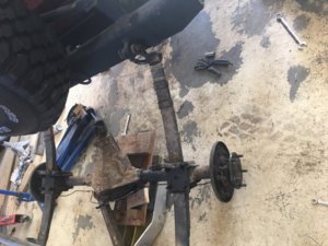
For the rear, I hope to add disc brakes with a 5x5.5" bolt pattern. The rotors need to be ~11.75" so they fit under 15" wheels.
I have a set of 1988 Caddy calipers with integrated E-Brake.
However, I have run into a snag.
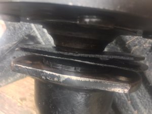
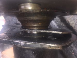
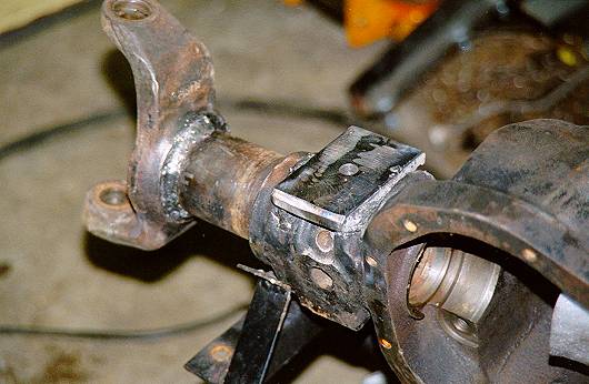
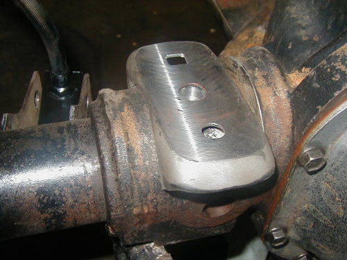
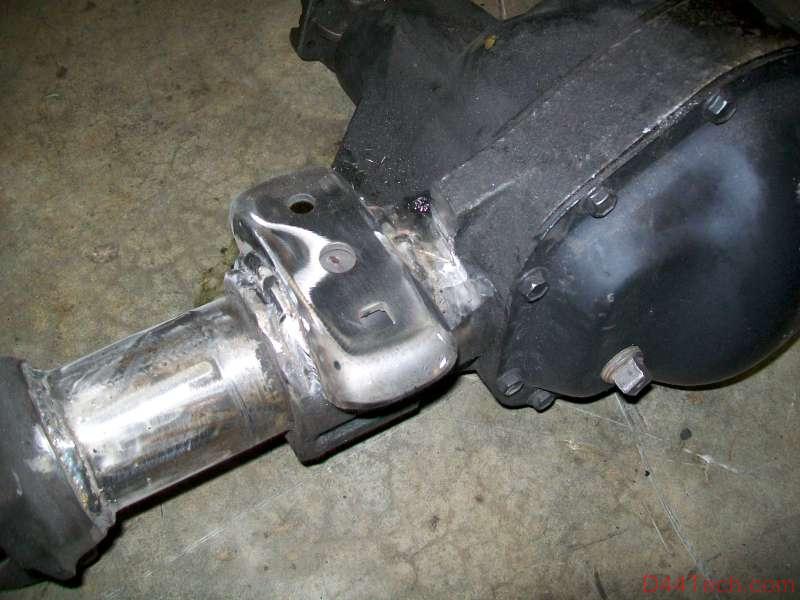
The OD of the new axles (about 7 1/8")( does not fit into the hat for the rotors I have from either the CJ, the waggy, or the Scout.
Went to the store and tried some rotors from a 77-78 Bronco. Same problem. The ID of where of the rotor where the rotor hat is just under 7".
Really don't want to grind down the OD of the new axles so they fit into the rotor hat.


I know they sell rear disc brake conversion kits for CJ's and Scouts.
Just trying to figure out which rotor to use.
Maybe I have to use a rear rotor 5x5.5" that was designed with a drum brake type E-Brake?
Any ideas?
I have a set of 1988 Caddy calipers with integrated E-Brake.
However, I have run into a snag.
The OD of the new axles (about 7 1/8")( does not fit into the hat for the rotors I have from either the CJ, the waggy, or the Scout.
Went to the store and tried some rotors from a 77-78 Bronco. Same problem. The ID of where of the rotor where the rotor hat is just under 7".
Really don't want to grind down the OD of the new axles so they fit into the rotor hat.
I know they sell rear disc brake conversion kits for CJ's and Scouts.
Just trying to figure out which rotor to use.
Maybe I have to use a rear rotor 5x5.5" that was designed with a drum brake type E-Brake?
Any ideas?
Last edited: