Bent Fab CH2

What headers are those. Look like they'd work on the buggy I have in the shop.
beware none of the bolts are the correct size and the flanges are “close enough” lol. I mean they are $77 so cheap enough to cut up vs $500 set. Haha


Mig monday
shock tabs for the rear axle.
6AC239CF-C302-44E0-9D3B-4BF8BC41FAA6.jpeg
F4DA3CD3-6CE4-4D76-BA7E-D2DE22B64C0E.jpeg
B8274D89-8CE0-4854-943D-1274AE70A84C.jpeg
0B2C501B-337B-48D2-8C74-A4152A446916.jpeg
941B7188-0760-4E22-AABE-4FF758A27AB5.jpeg
C8995C73-022E-428C-8858-6945ECCB8873.jpeg
 
A weekend of set backs. Wish I had more progress pics but o well. We made progress but it was a battle.
We got the rear struts mounted and checked for clearance and everything was fine.
Then started on the front.
We noticed 2 of the struts wouldn’t collapse the full amount.
According to ORI, there is supposed to be .7” of polished shaft showing at full compression. 2 of the struts did this easily with zero n2 pressure in either chamber.
The other two had 1.875” shaft showing, despite our best efforts and creativity in collapsing them.

After a late Friday night call to Jensen Bros, and despite my years of conviction and proclamation to not ever work on/tune ORI’s, I had to open two of these up to figure why the wouldn’t compress.
The bump piston, came out of its bore in the top of the main piston, flipped over and was jammed between the piston and top valve/top cap.
Waiting to hear back from ORI/Jensen bros, but initial response is that all parts should be covered under warranty, despite Steve not being original owner of these struts.
We removed the bad parts and reassembled the struts now being able to fully compress them. It was on to mounting the front struts, cycling everything and checking clearances.
The first initial mounts seemed to be great, but during articulation, the body hit the lower front chassis tube work and prevented full droop, during articulation only.

that ended our Saturday night.
This morning we removed the racks holding those shock brackets, and started looking at where else they will fit, and fully articulate without issue.
Re-Used the tabs in new locations, just tacked to figure out where they would work.
Once we cycled everything, we had to make all new tabs/brackets for the front struts.
Uppers are done and installed, lowers are tacked, final ones just need to be cut and installed to replace the mock up tabs.
 
That’s pretty dang cool they’re gonna warranty it even though he didn’t buy them new himself!
 
That’s pretty dang cool they’re gonna warranty it even though he didn’t buy them new himself!
We should hear back tomorrow for sure. We honestly didn’t expect Jensen bros to answer the calls/texts that late Friday. That said, I have nothing but good things to say about ORI and Jensen bros, despite me personally not liking ORI’s, haha. This could be a story in the “I eat crow and it tastes terrible” thread. Haha
 
I met the Jensen bros at KOH a while ago. They were tuning ORI products for free and doing it out of the back of a rented RV. Super friendly and knowledgeable. Didn't hesitate for 1 second to show me the insides of the product and what they were working on.

I'm not a fan of ORIs but if I had to work on/buy some I'd definitely give them my business.

Do you know what's your belly height at full bump ?
20” belly at RH, 13” belly at full bump. 7” up, 9” down split. Steve may lower to 6” up/10” down and 19” belly @ RH when it’s done and after shakedowns.
 
We got confirmation that BFR refunded Steve for the plate work that he returned.

to be transparent, and for clarity, I improved these areas of my link locations vs the BFR link locations. This is separate from the bolt hole issues.

In the front, I changed both static and travel Anti-dive( pro squat) geometry and improved the pinion angle change thru travel. This also improves caster migration thru travel.

In the rear, my link locations improved both static anti squat, more importantly anti squat change in droop ( for climbing more vertical style obstacles) as well as I lessened the pinion angle change thru travel.

The BFR locations were “ok” (not great) static, but definitely had room for improvement thru travel
 
I mean, unless he posts the before and after numbers and explain why they are better, I wouldn't start bashing the product. And I know that @Mac5005 is very knowledgeable about this stuff. He also knows that by putting a 4sp atlas in there and moving the engine 6"+ forward and changing the location of the axles, you end up moving the COG. COG which is where the whole original geometry is based on.

@rockcity I'll happily offer you a ride in my chassis with the "not great" geometry and let you feel how it works IRL. I could get more technical too, but Tim has his own (and somewhat unconventional) way to set them up and seeing it work always makes you a believer. I have a few chassis builder friends that pulled the tape measure under my rig because of how it works.

PS : It's not a secret that I'm friends with Tim from BFR, and despite the snafu of the brackets, I believe he did try to make it right by reimbursing Steve.

I really enjoy the build and seeing Scott's and Steve's take on the chassis, don't want to drag this into a geometry argument, just trying to make sure people see the product in action like it's meant to be put together in the first place before taking a stance on its performance.

Carry on.
Here is my take on the #’s.
The drivetrain length plays very little into the real geometry numbers. The height affects it, but the length completely doesn’t. Maybe slightly based on link length split front/rear, based on engine location, but not enough to make up for the deficiencies.

I ran the numbers 100% on BFR brackets, but I didn’t save the file. I don’t care to bc I saw the flaws. Mentally once I see the flaws, and potential improvements, I don’t care to have the file, bc it’s of no use to me. If Tim @ BFR wants to post his specific geometry #’s that’s on him.

it’s not my prerogative to point how the how and why of his errors. Not for free. That’s his due diligence on his product.

I’m not doing this to bash Tim, otherwise this would read very differently. There were aspects of the geometry that weren’t up to my standards, I brought them up to my standards. Steve trusts me enough to complete this, and trusts my expertise and experience for it to be correct. Steve knows my standards and my knowledge which gave me this enormous opportunity. I’m just here to share that with my Nc4x4 family, just as I do with nearly everything.

short version: too much pinion change in both front and rear. Static and dynamic anti’s were meh.

Rear had low static AS, and it increased to “ok” in droop. That’s great bc it would never hop while climbing, but also lessens the forward bite at suspension positions near ride height.

I’ll be more than happy to post screenshots of my final geometry numbers and specific locations of the links, if that is pertinent to the transparency of this thread. If it does nothing to add value, then I see no need to post.

my geometry numbers used to just be theory based on vehicle dynamics and principles based on what I found didn’t work.

After several suspension set ups that clearly worked far better, confirmed my theories. That’s the proof I need.

I have posted my theories on here in the public for years now. I wouldn’t take that risk if I didn’t have data both in principle/theory and real world application.

most of that knowledge, wasn’t publicly discussed by the people in the know until after 2008-2012 IIRC. Those that knew prior to then, weren’t talking about publicly anyway.

I’m not here to bash Tim, I’m just being transparent.

I would say if Tim would like to have a chat about how to make his setups better, I’d be willing to chat for free.

However after the bolt/ holes/misrepresentation and other items that were sold as ready to go, however fell short, I doubt Tim wants to talk to me, and I really don’t give .02 to talk to him. The response that the zinc coating on the bolts was the likely culprit solidified my position.

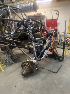
so back to progress. Here are the lower shock brackets, on the outer “forward” side of the mount. Need to add the teardrop plates and the final fit up.


D21C6DD9-797C-442B-BAB7-44EB9E9FC785.jpeg
C7BEF37C-66E6-47E8-AEA5-16A90ADA757A.jpeg
C345EF40-4DC4-40A9-8E74-FBED2EA0D7AC.jpeg
6691785C-F6D8-4E22-BDA0-4F4AF0CA8A99.jpeg
3038C60F-5C6A-4A6D-8AF7-A17DE7784EEC.jpeg
821C91B1-24A7-4F4E-8578-FB08B8761A40.jpeg
29DEE3D4-1138-40BB-BE74-27184E653345.jpeg
 
Last edited:
You’d think with the high $ cost of that chassis that the geometry would be better. Unless you made adjustments for east coast and specific trails to be ridden.
Kinda but Not exactly.
The Changes work better in general all around.
You can get away with more AS increase in droop for u4/sandbox bc less climbing waterfall style stuff and more winching those tough obstacles. Pinion deviation and plunge is still an issue no matter the desired application. Desert racing typically runs lower anti’s just to give more throttle/brake induced pitch changes on command. This is for getting the nose up/down based on upcoming obstacles/whoops/g-outs etc. it’s not that the sandbox guys want lower AS, it’s a side effect of getting the bump forces to travel more through the shocks and less thru the links ie: more horizontal links and more wheel recession towards bump.

low HP and low traction would mean low torque reaction force, but that’s neither here nor there.
 
Another observation. The shock hoops are relatively “low” compared to 14/16” travel shocks/struts.

with 7” uptravel and the 16” ORI that have a short compressed height of 23.2, it’s still a battle to get the shocks between the hoop and the axle tube.
The bolt centerline for the lower mount for the struts is 1/2” below the top of the axle tube.

I can’t imagine trying to get a 16” coilover in the same spot, as the compressed height is 2-3” taller than the same travel ORI.

the original location had the shocks rotated up and in on the hoops which solved the vertical distance problem, but didn’t clear the lower front frame tubing during full articulation.
Another potential solution was to mount the shocks outboard and up on the front hoops, but no one liked that location due to the vulnerability of the top cap and body of the shock placed there.
Knowing Steve actually wheels and will likely flop, it just didn’t seem like an appropriate location to use.
As well, up and outboard of the hoop shock mounting would require building significant tube or plate structure to protect the top cap, and in my opinion would run the front look of this buggy.
 
To better explain the above post.
@7” uptravel and 20” belly, at full bump, my best guess there is 25.25” from the axle tube to the shock hoop. ( given slightly difficult to measure with shock installed).

at minimum for ORI, 1.25” is necessary to clear the eyelet from the mounting surface. I built for 1.5” so that there is .25” clearance at the tightest spot as it articulates.

so 25.25- 2.5(min) leaves 22.75” to mount the shock. With our upper shock mount, this is 22.5”.

the 16” ORI fully compressed is 23.82”. Showing the reason the bolt centerline of the lower shock mount is actually lower than the top surface of the axle tube.

keeping the same uptravel or more, while lowering the belly isn’t practical with the height of these shock hoops.
Even most 14” shocks, (with the exception of air shocks) have a greater compressed height than that 22.75” distance.

another way to explain it, measuring from floor,
the top of the axle tube is 29.375” @bump, and the bottom of the shock hoop is 51.5”, leaving room for 22.125” long shock fully compressed (if the shocks were vertical).


8947B04C-82AA-43BD-9488-FA87D06911FA.jpeg
A604711F-5393-4A87-9532-7392FD8F4F10.jpeg
DACC766B-210A-4538-834B-43BB0E01EF82.jpeg
77BA28CB-A16E-4C3C-BF42-6AC739BCFCF8.jpeg

6F67AA99-5CAD-4E11-B976-62101651BCF0.jpeg
 
Last edited:
today marked day 15 of the build. (Only counting days in the shop, not calendar).

We were only able to squeeze work in this afternoon. Finally got the front shocks all mounted and done. Checked clearances with steering and for the struts during full articulation.
Also cut up the driveshafts in order to shorten and remove the double cardan on the rear and lengthen the intermediate shaft for the front.
The front shaft from carrier bear to axle remains the same from before.
AC9AFAC2-4240-433D-A17C-46FC5D71F43A.jpeg
6A61C391-47E7-4F67-90F9-5C03B9F37A36.jpeg
7EB00905-6EDA-4DEF-9154-8F301EFFC5AD.jpeg
FBBC2DA0-E9FB-4C74-A0D6-2A69C362F2BB.jpeg
673D6DF6-1EE5-4FC1-BADF-36208A2C6558.jpeg


2FF52947-F813-4FB8-B129-0C8056D8D77B.jpeg
760F1B11-6E69-4E85-930C-795B1D242AF5.jpeg
 

Attachments

  • A519E591-9A97-4FB3-A1A0-06E44A5B548A.jpeg
    A519E591-9A97-4FB3-A1A0-06E44A5B548A.jpeg
    171.7 KB · Views: 109
Last edited:
What a weekend. Got the rear bed tube work all done, radiator measured, and fluid coolers mocked up.
Got exhaust done to the end of the muffler.
Had a seal fail on my tubing bender after making 1 of 2 bends we needed. Thankfully rode over to @ORV design and fab to use his bender to save the day(weekend).
Sam came down and tig welded the exhaust, and it looks way better than I could have done on 16ga.
Big list of parts to order after an awesome weekend in the show with great people. Thanks to @BRUISER for stopping by today.
Also got the new weld yoke in for the rear driveshaft, so we were able to ditch the double cardan and go to just single 1410 joints at both ends of the rear shaft. All welded up and installed. Clears fine and 4° of pinion change total thru 16” travel.
Photo dump.
485E376F-0EAB-4627-898E-04CA6316F451.jpeg
89636D9E-28DB-460B-92AE-D9570C721BA8.jpeg
BFF0C59D-B17E-4C11-830E-1C16CB9792E5.jpeg
67638555-E90A-485D-BE35-A8C936A6950E.jpeg
6C0203A1-D9DC-4CB4-AEA6-FAFA0654C76A.jpeg
0BAEF333-47C2-48AF-AB5D-1E1567AC3EE8.jpeg
85B3AF4F-E425-40C7-811F-0BC19BDEED7D.jpeg
B366FE96-22ED-4D0E-B158-49A7C43E1D7E.jpeg
ABA3480F-22BB-4811-A1B1-DB3E7E2CCBBF.jpeg
6F596962-AA14-4667-A306-25A62413EAD7.jpeg
 
Last edited:
Got the seats mounted, tilt wheel column, orbital mounted, throttle pedal mounted, and brake pedal done.

only thing we ended up keep from BFR was the master cylinder mounts and brake pedal and pivot.

The orbital mount was in a terrible location for plumbing, and just overall location. The BFR throttle assembly doesn’t work for drive by wire. ( well it’s advertised that it does, but requires using a cable throttle to a remote mounted new sensor, and reflashing the ecm for the new aftermarket sensor, so does that actually count for working with dbw?)

just mounted the oem dbw pedal, may rework the pedal in the future to make it pretty.

seat mounts are to get the most room not only for head/body but also for feet and thigh height for good ergonomics for the pedals. Some of my tig work on these that will never ever be seen again lol.

A894A944-E4D8-4969-B3F5-C4D20E65A617.jpeg
4DE56309-4C23-4F9B-9642-E6D0778F504E.jpeg
613B478F-BEAF-4E8C-BA15-BC9AB1466023.jpeg
9C6860A7-56A4-422B-BDDD-FE69E1F06AF5.jpeg
510FABB9-5283-4F93-999B-A5F54740CE97.jpeg
B07530EE-DC87-4DC0-AD10-8615F0011CFD.jpeg
265804A9-81E8-4B90-9933-625D7F5A5946.jpeg
93B3F696-A362-4619-8F2B-79B4945AEC37.jpeg
1EC7AC83-954C-48C6-A6B2-FEC2CC3324F5.jpeg
90517C73-B44E-4B9C-85B8-2ABC2041058E.jpeg
01C1D79E-237F-47D4-BA7E-0F84B6A016DF.jpeg
2AAE3E62-F92B-428F-837B-A9BA96A8FB2C.jpeg
6763B885-497C-402E-9939-6DD74511B1AE.jpeg
9FA6B745-D25E-49AD-AE01-21B180B2B165.jpeg
 
Back
Top