Now that the driveshafts are installed, time to work on the brakes.
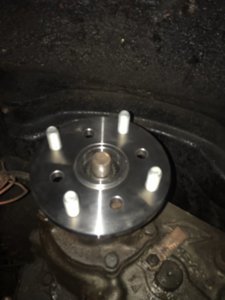
This is what is currently in the CJ
View attachment 289157
Since the CJ now was Waggy disc calipers up front and 1986 Caddy rear calipers, some changes are needed.
Would like to try to stay away from HydroBoost if possible, as to keep things simple.
There is the Corvette MC and booster assembly and their is the 1978 Mercury Marquis options for the brake booster/master cylinder.
The E350 MC is good, but was designed for a front and rear disc setup
Also heard about dual vacuum brake booster assemblies.
If possible, I would like to hear what experience you had regarding going to bigger disc front and rear.
Also, they make a proportioning valve that is designed for a disc/disc stetup
Thanks in advance


.JPG")
.JPG")